Engineering Insights
Injection-Molded Surface Gloss Variation: How to Separate Mold, Material and Process Factors
A gloss difference is an observation, not a root cause. This guide helps buyers define the requirement first, then investigate mold, material and process factors without guessing a universal setting.
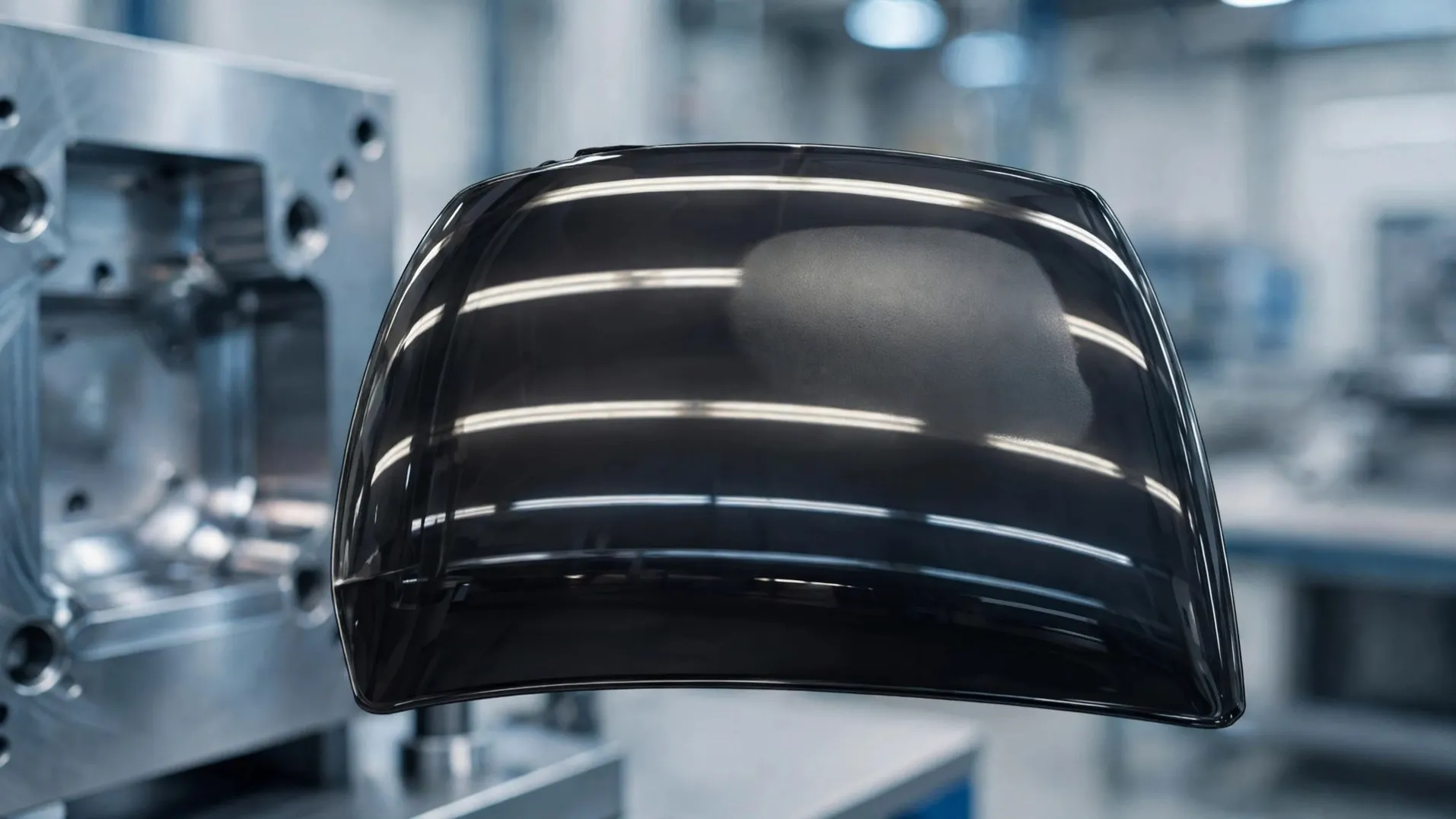
A molded part can meet its dimensions and still be rejected because one area looks duller, shinier, or different from the approved sample. The first useful question is not “Which setting should we increase?” It is “What appearance is required, under what viewing condition, and where does the difference occur?”
Gloss variation can be related to different flow behavior at the mold wall, cooling, shrinkage, mold-surface condition, or material and process changes. Similar-looking defects can have different causes, so agree on the visual standard and map the difference before selecting a correction.
Define the visual requirement before diagnosing it
“Glossy” and “matte” are not measurable acceptance criteria by themselves. Before a trial or supplier change, agree on:
- which surface and zone are critical;
- the viewing direction and lighting condition;
- the acceptable appearance range or approved reference sample;
- whether the concern is gloss level, a local patch, a flow band, a texture mismatch, or a sink/geometry feature;
- how the team will compare samples and who records the decision.
If a measured gloss value is required, the parties should agree on the instrument, geometry, locations, and method. The value is meaningful only when the method and surface are defined. Do not select a generic gloss number from another product and treat it as the specification.
Map the appearance difference on the part
Mark each sample with cavity, material lot, machine, date, and trial condition. Photograph the same zones under consistent lighting and orientation, alongside the reference sample if available. Record whether the mark appears:
- in the same place on every cavity;
- only on one cavity or one production lot;
- near the gate, a weld line, a rib, a thick section, or the end of fill;
- parallel or perpendicular to the flow direction;
- only after a material, tool-maintenance, or process change.
A defect that follows a cavity location may point toward tool-surface or cooling differences. A defect that changes with material lot or process condition may call for a different check. These patterns guide the investigation; they do not prove a root cause.
Review the mold surface and the molding history
Mold texture, polish, contamination, and wear
Compare the affected region with the approved surface specification, reference sample, and adjacent cavity surfaces. Check for residue, release-agent buildup, damage, wear, inconsistent texture, or a difference introduced during maintenance. If a texture or polish correction is considered, record the existing condition and verify the intended surface with the responsible tool engineer before material is removed.
Flow, venting, and cooling
Compare the mark with the fill pattern, gate and runner arrangement, likely meeting fronts, cooling layout, and local wall thickness. A flow-related surface mark can resemble a mold-finish issue. If the region is a last-to-fill area, venting may be relevant; if it aligns with a thick transition, shrinkage or cooling may need review. Do not assume that a visual patch automatically means poor polishing.
Material and process
Confirm resin grade, colorant, material lot, drying and storage records where relevant, and any permitted regrind. Compare actual molding records around the time the defect appeared. Consider whether the melt and mold conditions, fill profile, pack behavior, or cycle changed. Use the resin supplier’s guidance for that grade; settings from a different polymer or part are not a reliable recipe.
Autodesk describes a gloss mark as a dull patch on a glossy surface and relates gloss differences to flow behavior at the mold wall, cooling, and shrinkage. Its troubleshooting suggestions are starting points for investigation, not universal instructions. A change such as drying material, slowing fill, or adjusting back pressure should be made only when the evidence and material guidance support a controlled test.
Run a comparison that teaches you something
Write down one likely cause and the result that would support it. Hold the other relevant conditions as constant as practical and compare against the baseline sample. For example:
- If the difference follows a cavity after cleaning and the same process, examine the mold surface and cooling path.
- If it follows a material lot, verify material identity and condition before changing the tool.
- If it changes with a controlled process adjustment, confirm the change does not create a new defect or affect dimensions and function.
- If it remains tied to a last-to-fill region, review flow and venting evidence together.
Use the project’s agreed acceptance criterion. A visual improvement that falls outside a specified texture, color, or dimensional requirement is not a complete resolution.
For the separate question of a transparent automotive lens and a transition between clear and textured zones, see Automotive Light Cover Mold: Clear and Textured Surfaces. This article addresses general molded-part gloss variation rather than optical performance.
Questions buyers ask
Should we increase injection pressure to improve gloss?
There is no universal answer. Gloss can vary with material, flow, cooling, mold finish, and process conditions. First define the visual requirement and map the defect; then test a supported hypothesis under controlled conditions.
Is a dull patch always caused by poor mold polishing?
No. Flow behavior, cooling, shrinkage, venting, material condition, and local geometry can produce similar observations. Compare the patch location, cavity, lot, and process history before assigning the cause.
Can we approve a part by comparing it with a photo?
A photo is useful for documenting location, but lighting, camera exposure, angle, and display settings can alter the appearance. For acceptance, use the agreed viewing or measurement method and a controlled physical reference where needed.
What should I send for an initial review?
A non-confidential overview can include the affected zone, surface requirement, reference sample status, resin grade if shareable, cavity/lot pattern, and recent changes. Do not send customer-identifying images or proprietary CAD through a public contact channel.
To discuss a molded-part appearance or tooling question, begin with a non-confidential description via the project inquiry page.