Jul 30, 2026Technical Case Studies
Case Study: Automotive Lighting Mold with Optical Clarity and Textured Surface
Some injection molded parts look simple on the outside, but become extremely difficult once optical, cosmetic, and tooling requirements are combined. This automotive lighting project was one of those
Some injection molded parts look simple on the outside, but become extremely difficult once optical, cosmetic, and tooling requirements are combined.
This automotive lighting project was one of those cases.
The customer, a Tier-One automotive supplier, brought us a corner light assembly component after several previous tooling attempts had failed. The challenge was not only to mold the part. The challenge was to achieve optical clarity and fine surface texture on a complex geometry without visible defects, transition marks, or loss of appearance quality.
For many mold suppliers, these two requirements create a conflict.
Optical clarity requires precise surface control, stable geometry, clean transitions, and minimal optical distortion. Fine texture requires controlled surface treatment and careful separation of textured and non-textured areas.
Trying to force both requirements into the same mold surface strategy often leads to defects.
At Jeancen Mold, the solution was not to lower the requirement. The solution was to redesign the mold structure around the real technical conflict.
Project Overview
Item | Detail |
|---|---|
Client | Tier-One Automotive Supplier |
Application | Automotive Corner Light Assembly |
Industry | Automotive Lighting |
Main Challenge | Optical clarity + fine textured surface |
Core Solution | Insert segmentation + precision Wire EDM |
Result | First-trial approval |
Timeline | 45 days |
The customer had already experienced multiple failed attempts before contacting Jeancen Mold.
The previous suppliers could not achieve the required optical and texture quality at the same time. Some suggested reducing the optical requirement. Others suggested making the texture rougher or accepting a visible transition.
For an automotive lighting component, that was not acceptable.
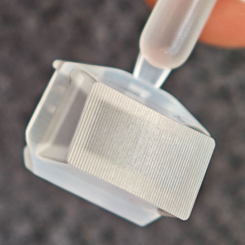
The Main Challenge: Optical Clarity and Texture on the Same Part
The most difficult area of this part was a surface zone that required both optical quality and fine texture control.
This is a challenging combination because optical areas and textured areas are usually treated differently during mold design and manufacturing.
Optical surfaces require:
- High surface consistency
- Minimal distortion
- Controlled machining marks
- Clean transitions
- Accurate cavity geometry
- Stable molding conditions
Textured surfaces require:
- Precise texture boundary control
- No unwanted transition lines
- Consistent texture depth
- Controlled insert matching
- Accurate alignment between textured and non-textured zones
When these two requirements meet in one local area, the mold design must control not only the shape of the part, but also the boundary between different surface treatments.
If the transition is not controlled well, the part may show:
- Visible texture transition lines
- Optical distortion
- Surface mismatch
- Flow or shadow marks
- Cosmetic defects
- Poor light transmission or clarity
- Failed visual inspection
This was the reason the previous attempts failed.
The part itself was not impossible. The earlier mold strategy was the problem.
Why a Standard Mold Approach Was Not Enough
A standard approach would try to machine the area as one continuous cavity surface and then manage the texture and optical zone through polishing or secondary adjustment.
That approach sounds simple, but it creates high risk.
When optical and textured areas are too close together, the moldmaker may lose control over the boundary. Excessive polishing may damage geometry. Texture processing may affect adjacent optical areas. Machining marks or insert mismatch may create a visible line on the final molded part.
In this project, lowering the customer’s standard was not an option.
The mold needed to achieve the designed optical and cosmetic result.
That meant the mold structure had to separate the conflicting requirements instead of forcing them into one uncontrolled surface.
Jeancen’s Engineering Decision: Split the Insert
After reviewing the drawings and surface requirements, Jeancen’s engineering team identified the key principle:
Do not try to solve two conflicting surface requirements with one continuous mold surface. Separate what needs to be separated.
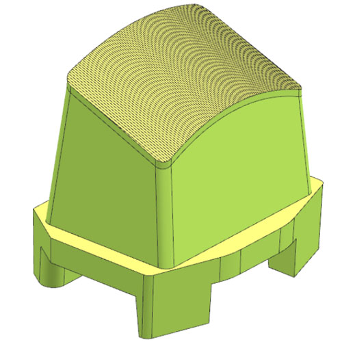
The textured surface was designed as an independent insert.
This insert segmentation strategy allowed the team to control the optical area and textured area separately, while maintaining the required fit and transition quality between them.
The goal was to avoid compromise.
Instead of asking the customer to reduce the optical requirement or accept a rougher texture, the mold was designed to support both requirements through better structure.
Why Insert Segmentation Worked
Insert segmentation created several advantages.
1. Better Control of Surface Boundaries
By separating the textured area into an independent insert, the boundary between optical and textured zones could be controlled more precisely.
This reduced the risk of uncontrolled transition marks and improved visual consistency.
2. More Accurate Machining Strategy
Different surface zones could be processed using the most suitable machining method.
The optical-related area could maintain the required surface quality, while the textured area could be controlled through a dedicated insert strategy.
3. Easier Adjustment and Inspection
Independent inserts make it easier to inspect, adjust, and validate the critical area.
If future optimization is needed, the insert-based structure also provides more flexibility than a fully integrated cavity surface.
4. Lower Risk During Mold Trial
When the mold structure matches the surface requirement logic, the chance of trial-stage defects is reduced.
This is especially important for automotive lighting projects, where visual acceptance standards are strict.
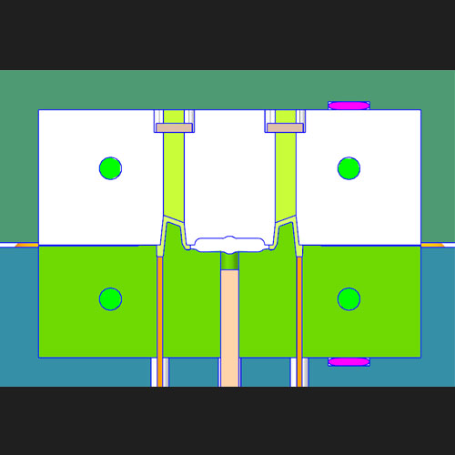
Precision Machining Strategy
The insert strategy alone was not enough. The manufacturing process also had to be controlled carefully.
Jeancen used a precision machining strategy focused on surface boundary control and insert contour accuracy.
Key actions included:
- Separating the textured surface as an independent mold insert
- Extending the high-speed machining area by more than 0.5 mm
- Using precision Wire EDM for final insert contours
- Holding insert contour tolerance within ±0.005 mm
- Controlling the transition area to avoid visible mismatch
- Inspecting the critical surface zones before trial
The 0.5 mm machining extension was important.
If the machining area stops too close to the boundary, the final molded part may show a transition line. By extending the machining area beyond the immediate boundary, the team created a safer and cleaner transition zone.
Wire EDM was then used for the insert contour to maintain tight dimensional control.
This combination helped achieve both appearance quality and assembly precision.
Why Wire EDM Was Critical
Wire EDM was selected for the final insert contour because the boundary precision was one of the most important risk points in the project.
For this type of automotive lighting component, a small mismatch between insert and cavity can become visible on the final part.
Wire EDM helped control:
- Insert contour accuracy
- Boundary alignment
- Matching between insert and cavity
- Local dimensional repeatability
- Risk of visible transition defects
The purpose was not only to manufacture the insert. The purpose was to protect the final visual and optical result.
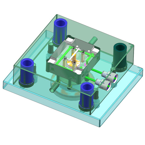
Mold Trial and Result
At the first trial, the part passed optical inspection.
The key result was not only that the mold produced a part. The result was that the critical optical-texture combination area met the customer’s acceptance standard without the repeated defect patterns seen in previous attempts.
Project outcome:
- First-trial approval
- Optical inspection passed
- Texture boundary controlled
- No visible transition defect in the critical area
- No need to reduce optical requirement
- No need to lower texture requirement
- Tooling completed within the project timeline
For the customer, this meant the project could move forward without another tooling restart.
For Jeancen, the result confirmed the value of front-loaded mold design logic.
What This Case Shows About Automotive Lighting Tooling
Automotive lighting components are often more complex than they appear.
They may combine optical performance, cosmetic quality, tight tolerances, textured surfaces, assembly features, and strict visual inspection standards.
In these projects, mold success depends on early engineering decisions, not only machining accuracy.
Important decisions include:
- Where to split inserts
- How to control surface boundaries
- Which machining method to use
- How to protect optical areas
- How to avoid visible transition lines
- How to inspect critical surfaces before trial
- How to maintain repeatability in production
A supplier who treats the part as a standard plastic component may miss these hidden risks.
A supplier who understands optical and cosmetic tooling requirements can identify them before steel is cut.
Why “It Cannot Be Done” Often Means “The Strategy Is Wrong”
When a previous supplier says a part cannot be done, it does not always mean the part is impossible.
Sometimes it means the mold strategy is wrong.
In this project, the problem was not solved by accepting a lower standard. It was solved by changing how the mold was structured.
The engineering logic was simple:
Do not force conflicting surface requirements into the same uncontrolled zone. Separate the insert, control the boundary, and apply precision where it matters most.
This is the kind of practical tooling judgment that comes from real mold design and trial experience.
Lessons for OEM and Tier-One Automotive Buyers
For automotive lighting and appearance-critical molded parts, buyers should not evaluate mold suppliers only by quotation price.
They should also ask:
- How will optical and textured areas be separated?
- Where will inserts be split?
- How will transition lines be avoided?
- What machining method will be used for critical contours?
- How will insert matching be inspected?
- How will optical clarity be verified?
- What happens if the first trial shows a surface mismatch?
- Does the supplier have similar experience with optical or cosmetic parts?
These questions help reveal whether the supplier has a real tooling strategy or only a basic moldmaking plan.
Key Takeaway
This project was successful because the mold design respected the real technical conflict.
Optical clarity and fine texture require different controls. When they are forced into one uncontrolled surface strategy, defects are likely.
Jeancen solved the issue through:
- Early DFM review
- Independent insert segmentation
- Extended high-speed machining area
- Precision Wire EDM contour cutting
- Tight insert tolerance control
- Careful optical and cosmetic inspection
The result was first-trial approval after previous failed attempts.
For automotive lighting projects, this is the value of experienced mold engineering: not only making the part shape, but controlling the hidden surfaces, transitions, and risk points that determine whether the part can pass customer evaluation.
Need Help with an Automotive Lighting or Optical-Texture Mold Project?
Jeancen Mold supports high-precision injection mold design and manufacturing for automotive lighting components, optical parts, textured cosmetic components, clear PC / PMMA parts, and appearance-critical molded products.
If your project involves optical surfaces, textured areas, complex inserts, tight visual standards, or previous tooling failures, we can help review the mold risk before steel is cut.
Send your drawings, 3D files, or tooling concerns to:
info@jeancen.com
Jeancen Mold helps buyers reduce tooling uncertainty before mold manufacturing begins — through practical DFM review, precision insert strategy, and production-focused mold engineering.