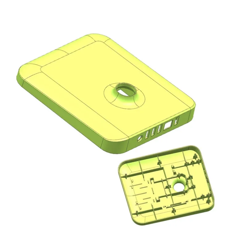
Enclosures that look right and fit right — before steel is cut.
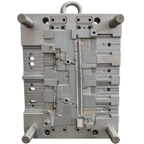
Jeancen designs and manufactures injection molds for precision plastic enclosures and housings — consumer electronics, POS devices and electrical components — with cosmetic surfaces and assembly fit reviewed before tooling.
Our mold engineers bring 12+ years of mold design experience to early DFM review, mold design and manufacture, T0/T1 trials, and injection production support.
Contact Us
Chat on WhatsApp
Who this page is for
Brands and manufacturers developing enclosures and housings for consumer electronics, POS devices and electrical components — especially teams whose housing must look clean, fit precisely and survive assembly and daily use.
You may have a finished housing design, or an intent with appearance level, key dimensions and assembly requirements still being settled. You do not need a fully locked design to start. You need a clear housing intent: what it encloses, what it must fit, and what the visible surfaces must look like.
Problems this page answers
Gate marks on cosmetic surfaces.
A housing can mold perfectly and still fail on appearance, because the gate leaves a visible mark exactly where the customer looks.
Deep ribs that trap air.
Thin, deep ribs are hard to fill and easy to trap air in — incomplete filling and burn marks appear where the structure needs strength most.
Zero-draft fits damaged at ejection.
Mating areas with little or no draft are prone to damage during mold closing and ejection if fit, alignment and ejection are not planned together.
Multi-snap and undercut ejection.
Housings with several snaps and undercuts need lifter and slider mechanisms that release cleanly — otherwise parts stick, deform or break on ejection.
Thin walls versus strength and warpage.
Larger flat housings trade thin walls against strength and flatness; without balanced cooling and wall review, warpage appears after molding.
Visible parting lines on cosmetic seams.
A parting line crossing a visible face reads as a defect, even when dimensions are correct — seam position and polishing must be decided before steel is cut.
How a housing DFM review works
Every housing is reviewed before tooling across seven aspects, as one connected pass:
1. Mold opening direction.
Cavity and core direction is set together with slider and lifter layout, so undercuts and snaps have a release path from the start.
2. Parting line position.
The seam is placed where it least harms appearance and assembly, and its polishing requirement is agreed before steel is cut.
3. Gate strategy.
Gate type and position are chosen against cosmetic requirements first — hidden or non-visible placement where the visible faces demand it — then checked for filling.
4. Wall thickness.
Main walls, thin sections and rib ratios are reviewed together, so filling, sink marks and strength are balanced instead of traded blindly.
5. Inserts.
Cavity, core and slider inserts, and their parting lines, are reviewed before tooling — including venting inserts where deep ribs need them.
6. Ejection.
Ejector positions and ejection method are reviewed against part geometry and draft, so ejection force is balanced and parts release without stress or deformation.
7. Cosmetic confirmation.
Polishing requirements, gate strategy and customer approval are aligned at the DFM stage, not discovered at T0.
Draft is reviewed area by area together with assembly function: non-critical molding surfaces and assembly-related faces do not get the same draft treatment, and the trade-off is stated before tooling.
Method 1 — Cosmetic surfaces without gate marks.
Gate placement starts from the visible faces, not from molding convenience. Where appearance demands it, the gate is placed inside a non-visible hole or in a hidden position, so the cosmetic faces stay clean.
Parting lines are controlled the same way: the main core and sliders are locked together and polished as a single block, so the seam does not read as a step on the visible face. On a router housing, this held the parting line under 0.03mm.
Method 2 — Deep ribs that fill and vent.
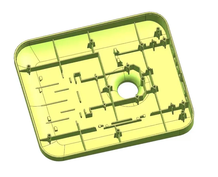
Deep, thin ribs are split into individual inserts where machining and venting demand it, with dedicated venting channels engineered into the inserts so trapped air has a path out instead of becoming incomplete filling or burn marks.
Beryllium copper (BeCu) is used on critical sliding surfaces where wear resistance matters for lifter longevity, and ribs behind lifters get clearance so they are not scraped during ejection.
Method 3 — Precision fit and assembly, held through production.
Zero-draft mating areas are treated as a fit problem, not just a machining problem: alignment, closing and ejection are planned together so delicate features are not damaged.
On a relay housing, zero-draft mating features were machined and aligned to ±0.005mm with high-speed CNC and slow wire-cut EDM.
Warpage is controlled with multiple independent cooling circuits rather than a single loop, and thin-wall sections are supported with high-toughness steel inserts where strength demands it.
Assembly fit is reviewed at DFM stage, so the housing that passes T0 is the housing that assembles at volume.
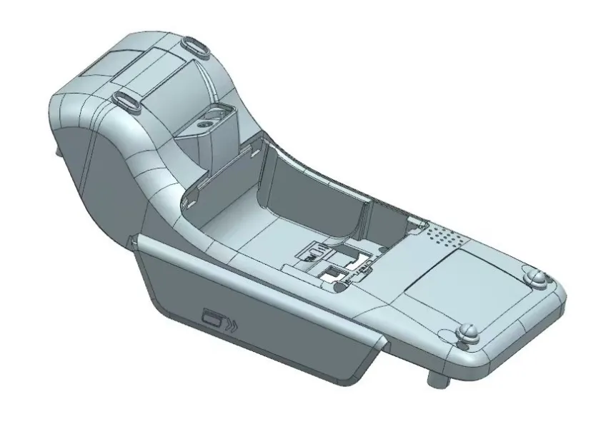
A POS terminal enclosure, reviewed before steel was cut
A POS terminal lower housing in ABS+PC (average wall 1.42mm) was reviewed before mold design.
The review caught four issues while they were still cheap to fix: a 0.62mm thin-wall area at risk of incomplete filling; several ribs over 60% of the main wall thickness, at risk of sink marks;
ribs behind the lifter without clearance, at risk of scraping; and three insert removal locations leaving thin steel sections on the core.
Each was corrected in the design direction — add material at the thin wall, rebalance rib thickness against the main wall, add lifter clearance, and optimize the insert geometry — before steel was cut.
The same enclosure's build solutions show the method in practice: an optimized pinpoint gate system for zero gate marks; a parting-line tolerance of ±0.03mm achieved with integrated polishing technology; a front mold angular lifter mechanism for complex angled-hole ejection;
a beryllium copper insert with conformal cooling for local overheating risk; multiple independent cooling circuits for warpage control; and high-toughness steel inserts for thin-wall section strength.
From review to stable production
Once the design is mature, it continues on Jeancen's NPI path: engineering front-loading (feasibility, DFM, risk checklist, simulation if needed) → tooling design and build (mold design, machining, assembly, pre-tryout check)
→ tryout and validation (T0, measurement, corrective actions, T1/T2 verification) → pilot run, release, maintenance and ongoing support.
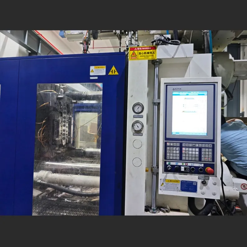
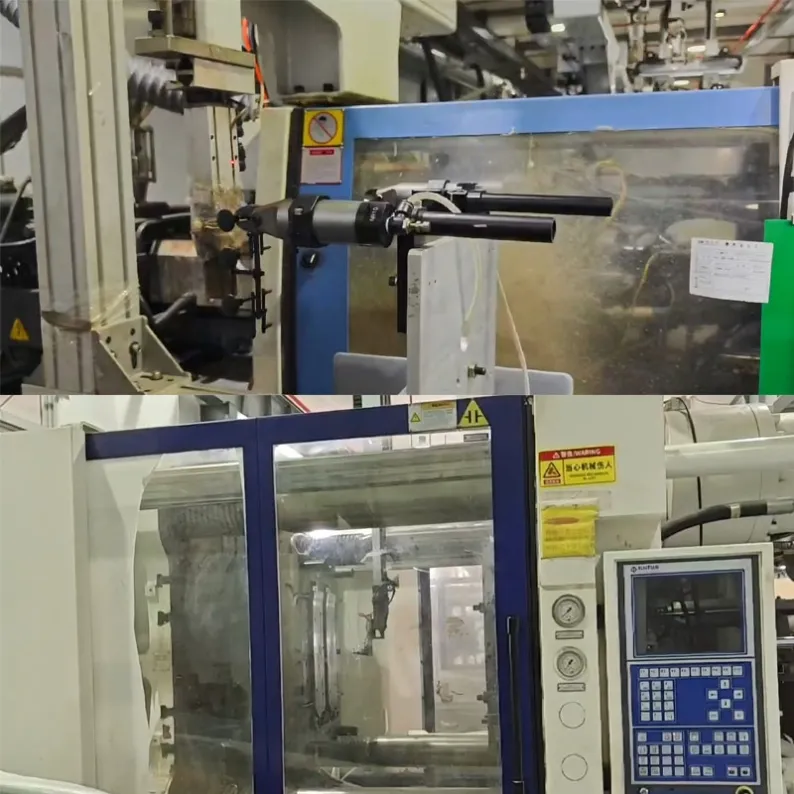
Factory
Jeancen is an integrated injection mold and injection molding factory in Xiamen, China. Our mold engineers bring 12+ years of mold design experience to early DFM review, mold design and manufacture, T0/T1 trials, and injection production support.
Materials and special requirements
Material direction is reviewed per project from PP, ASA, PA66+GF, PC/ABS, POM and TPU, against function, fit, appearance and cost for the specific part.
Special regulatory, certification, safety, material, precision or other exceptional requirements are reviewed case by case — not promised on the page.
How a project starts
1. Send your enclosure intent or design, plus appearance level, key dimensions, assembly requirements and volume direction. 2. Free initial DFM review: manufacturability direction, cosmetic and fit risks, and what the design needs before tooling — before any tooling commitment.
3. Tooling, T0/T1 trials and production support, including small-batch trial orders. 4. NDA available when required.