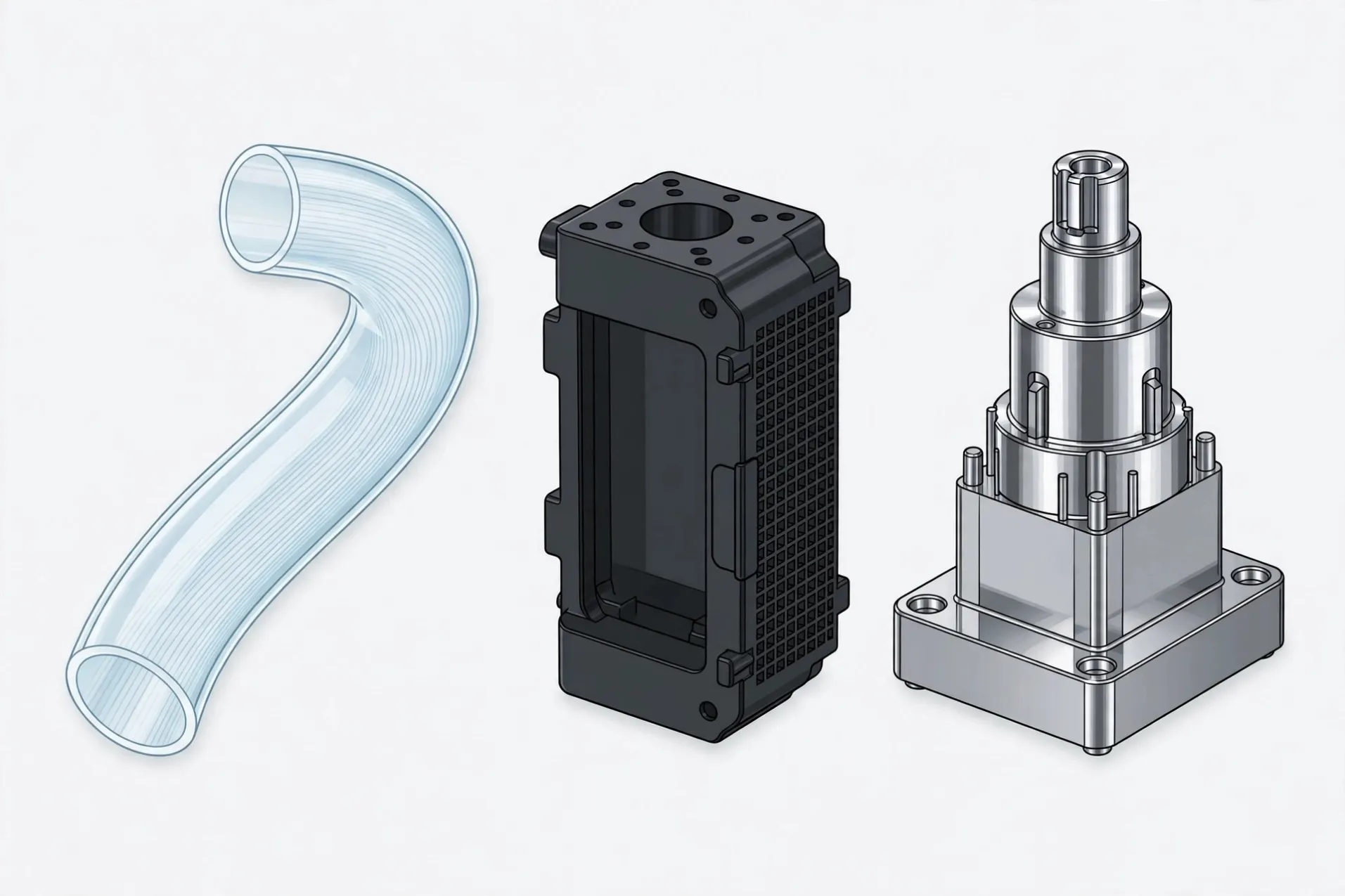
High-Precision Molds for Difficult Parts, Proven on Automotive Lighting
If your part is hard to mold precisely, start here. Jeancen designs and manufactures injection molds for difficult precision parts — where optical surfaces must stay clean, thin ribs must fill and vent, and mating areas must fit without damage.
Automotive lighting is used on this page as the proof of that precision level, not as the only kind of part we make. Our mold engineers bring 12+ years of mold design experience to early DFM review, mold design and manufacture, T0/T1 trials, and injection production support.
Contact Us
Chat on WhatsApp
WHY AUTOMOTIVE LIGHTING IS THE TEST, NOT THE TARGET
Automotive lighting is difficult in two different ways at once. An optical part fails on appearance if the surface has a mark, a seam step, or flash. A lighting housing fails on structure if air is trapped in deep ribs, if a boss cracks, or if a high flange deforms on ejection.
That is why this page exists. It is not a page only for car makers. It is a page for any buyer whose part is difficult to mold precisely, with automotive lighting shown as the difficulty benchmark. If your part is not automotive, the transfer section below is written for you.
WHO THIS PAGE IS FOR
Brands and manufacturers with a precision part that is difficult to mold — a clear or cosmetic part, a housing with deep ribs and snaps, a mating part with little or no draft, or a part where appearance and fit must both hold. You may be in shading, electronics, equipment, or another field.
You do not need a fully locked design to start. You need a clear part intent: what it must look like, what it must fit, and where it has failed or is at risk of failing.
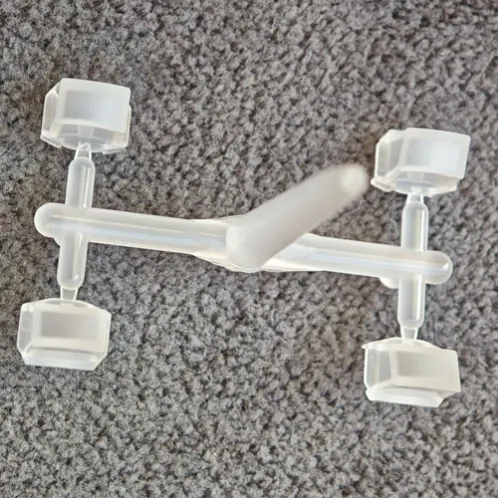
UPPER SECTION — OPTICAL: A LIGHT GUIDE THAT MUST STAY CLEAN
An automotive ambient light guide needs flawless light diffusion and perfect part clarity on a complex 3D curve, with a functional micro-textured optical surface. The difficulty is not only machining the texture.
It is machining it without risking the whole core plate, keeping it uniform right to the edge of the curve, and fitting the insert without flash on a clear part.
The method used was to isolate the risk. The complex optical face was engineered as a separate, high-precision insert, so the most critical feature could be machined and maintained on its own instead of risking the entire core plate.
The final insert profile was cut with slow wire-cut EDM to micron-level accuracy, giving a near-zero-gap fit with the mold base and a flash-free optical part.
For your part, the transfer is direct:
LOWER SECTION — CORNER LIGHT HOUSING: STRUCTURE THAT MUST NOT FAIL ON EJECTION
A high-precision automotive corner light housing needs full mold filling for a complex structure, with no post-processing, while holding assembly fit. Its difficulties are structural. Dense ribs trap gas and cause material shortage.
The methods used address each failure mode separately. A dynamic insert structure for ribs improves gas escape where dense ribs trap air. Wall thickness for the boss column follows a D:d ratio of 2–2.5:1, so the screw boss holds without cracking.
Asymmetric rib topology places reverse reinforcement in deformation-sensitive areas, so thermal deformation does not shift positioning.
For your part, the transfer is structural, not automotive: any housing, bracket, or assembly part with dense ribs, screw bosses, high flanges, or heat-sensitive positioning needs venting, wall-thickness, ejection, and thermal decisions made together at DFM stage, not discovered at T0.
IF YOUR PART IS NOT AUTOMOTIVE
Clear or cosmetic part
— use the optical section: surface isolation, texture or polish control, and zero-gap insert fit.
Housing or bracket with deep ribs
— use the corner light section: rib venting inserts, wall-thickness ratios, and lifter clearance.
Mating part with little or no draft
— use both sections: alignment, closing, and ejection planned together so delicate features are not damaged.
Part with snaps, undercuts, or high flanges
— use the corner light section: slider and lifter layout, dual-stage ejection, and deformation control.
Part where appearance and fit must both hold
— use the full review below: gate, parting line, wall, insert, ejection, and cosmetic confirmation decided before tooling, not at T0.
HOW A DIFFICULT-PART REVIEW WORKS
1. Optical or cosmetic face first.
Where the visible or optical face sits, how it is textured or polished, and how its insert fits without a step or flash.
2. Parting line and gate against appearance.
Seam and gate positions are placed where they least harm appearance and assembly, then checked for filling.
3. Wall, rib, and boss review.
Main walls, thin sections, rib ratios, and screw-boss proportions are reviewed together, so filling, sink marks, strength, and cracking are balanced instead of traded blindly.
4. Insert and venting review.
Cavity, core, slider, and lifter inserts are reviewed before tooling, including venting inserts where deep ribs need them.
5. Ejection and thermal review.
Ejector layout and ejection method are reviewed against geometry and draft, and thermal deformation is checked against positioning, so parts release without stress and stay in position.
6. Assembly fit confirmation.
Mating, snap, and assembly requirements are aligned at DFM stage, so the part that passes T0 is the part that assembles at volume.
Product 3D design is done by a long-term professional design partner; Jeancen mold engineers join technical communication and manufacturability review. Detailed product design, engineering analysis, prototypes, and design revisions are separately quoted.
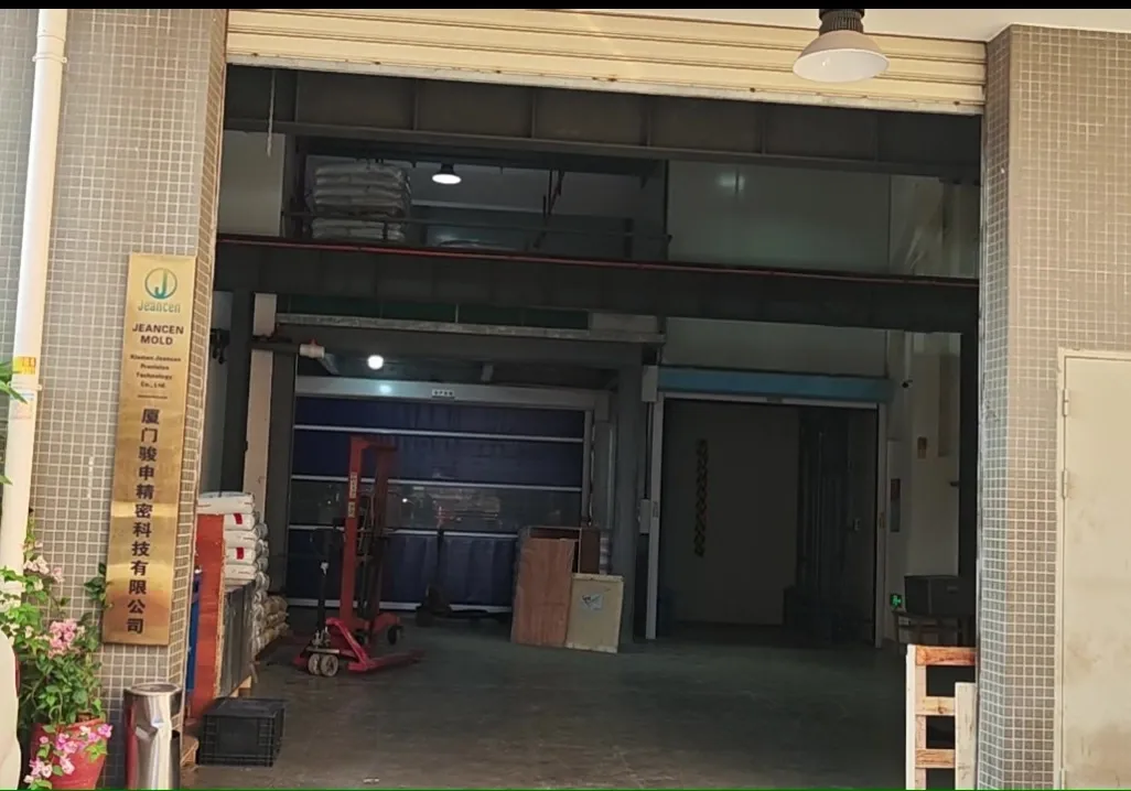
FACTORY
Jeancen is an integrated injection mold and injection molding factory in Xiamen, China. Our mold engineers bring 12+ years of mold design experience to early DFM review, mold design and manufacture, T0/T1 trials, and injection production support.
MATERIALS AND SPECIAL REQUIREMENTS
Material direction is reviewed per project from PP, ASA, PA66+GF, PC/ABS, POM and TPU, against function, fit, appearance and cost for the specific part. Special regulatory, certification, safety, material, precision or other exceptional requirements are reviewed case by case — not promised on the pa
HOW A PROJECT STARTS
1. Send your part intent or design, plus appearance level, key dimensions, assembly requirements and volume direction.
A difficult feature, a past failure, or a T0 problem is enough to start — you do not need a perfect file.