Engineering Insights
Injection-Molded Part Cracking: Diagnose by Location, Timing and Trigger
A crack during ejection, after assembly, and days into service can point to different failure paths. This guide helps teams preserve evidence and investigate before choosing a correction.
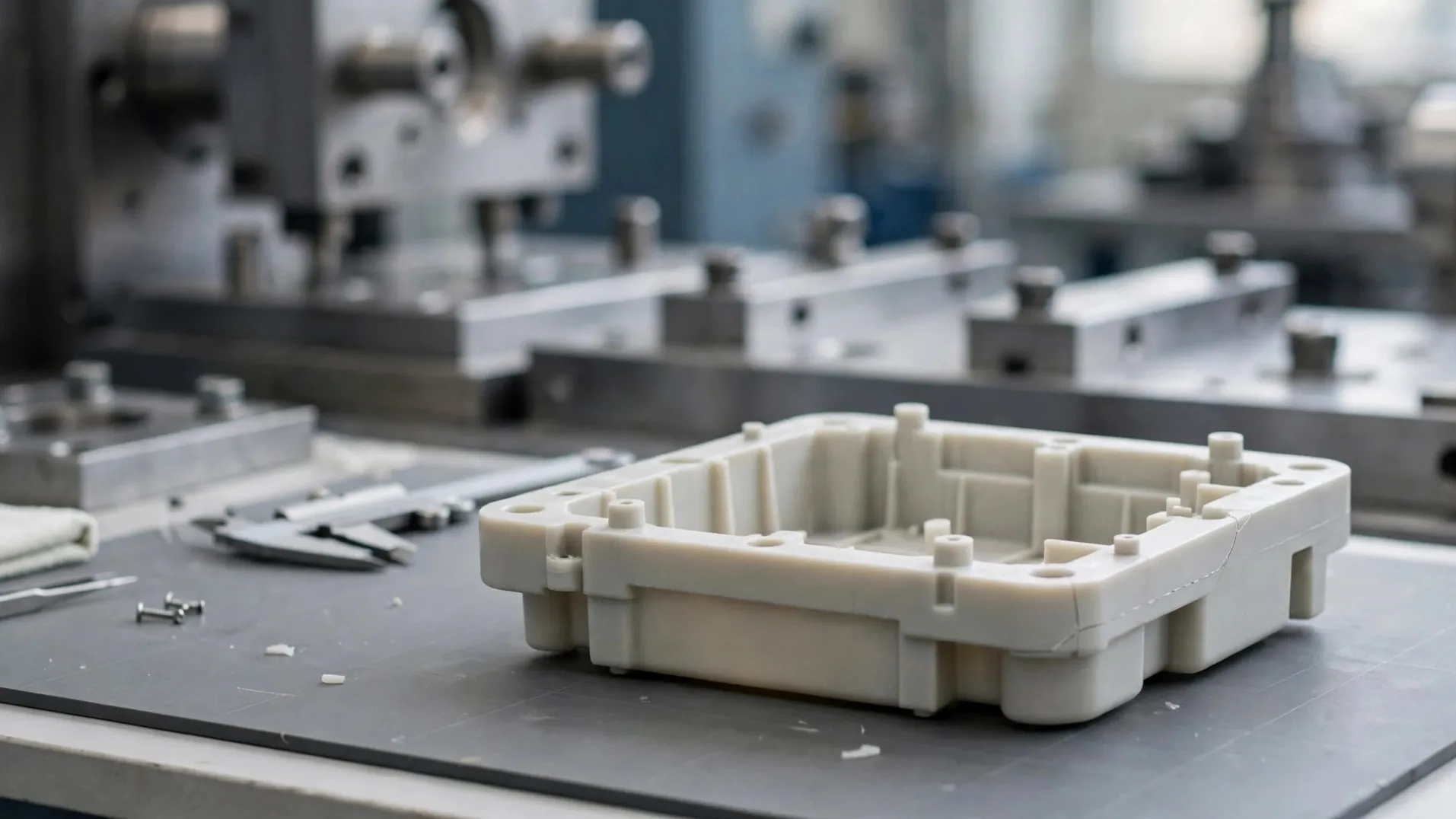
A crack is visible evidence of failure, but it does not identify the cause by itself. A part that splits as it leaves the mold needs a different first investigation from a part that passes inspection and cracks after assembly or days in service.
Before requesting a process adjustment or steel change, record where the crack starts, when it appears, and what event triggers it. That simple timeline can help the buyer and molding team separate competing explanations and choose a test that produces useful evidence.
Start with the failure timeline
When the crack appears | First questions to investigate |
|---|---|
During ejection or immediately after release | Is the feature sticking, locked by an undercut, or carrying an ejector mark? Is draft, surface texture, ejection balance, or vacuum release relevant? |
After assembly | Does a fastener, clip, press fit, or mating feature impose local strain? Does the crack start near a boss, sharp transition, weld line, or constrained area? |
After storage or a delay | Does the part change after cooling, conditioning, or exposure to a cleaning agent, lubricant, or other service chemical? Is the material and stress condition known? |
After a load, impact, or temperature cycle | Can the real use condition be reproduced? Are the load direction, temperature, and part orientation recorded? |
These are investigation paths, not diagnoses. More than one factor can contribute, and the first visible crack may be some distance from the location where stress became critical.
Autodesk’s Moldflow troubleshooting guidance identifies high residual stress, weld-line weakness, and differential shrinkage among possible cracking causes. It also cautions that a remedy for one molding problem can create another. The practical lesson is to test the cause that fits the evidence instead of applying a universal parameter change.
Map the crack before changing the process
For each failed part, record:
- part number and controlled drawing or CAD revision;
- mold identification, cavity, and trial or production date;
- resin grade, material lot, color, and any permitted regrind information;
- crack location and direction on a marked part image;
- whether the part was as-molded, trimmed, assembled, or exposed to another operation;
- time from molding to discovery, storage condition, and any known exposure;
- the actual molding, assembly, or use event immediately before failure.
Keep representative failed and unfailed parts from the same condition when possible. Do not sand, heat, chemically clean, or force the cracked part closed before it has been documented; those actions can obscure the fracture surface and the original condition.
When several cavities are used, keep cavity identity visible. A crack found in one cavity, across all cavities, or only in one material lot sends the investigation in different directions.
Check likely contributors in a controlled order
1. Ejection and release
For cracks that occur at ejection, compare the crack position with ejector pins, lifters, side actions, ribs, and regions that may retain vacuum. Review the ejection sequence, draft, texture direction, and whether release is balanced. An ejector witness mark next to a crack is a clue to test, not proof that the pin is the only cause.
A tool review may ask whether the part can release without bending a thin wall or loading a local feature. Do not change an ejector or polish a surface until the evidence shows what contact or restraint is occurring.
2. Geometry, flow meeting points, and local restraint
Mark thickness changes, sharp corners, bosses, inserts, knit or weld lines, and areas constrained by assembly. A crack at a flow meeting line may warrant review of the line’s location and the actual part requirement. A crack near a screw boss may call for checking the fastener, boss geometry, and assembly sequence as well as the molding condition.
Use the controlled drawing and the real assembly condition. A nominal CAD view cannot show every source of restraint in a finished product.
3. Material and molding history
Confirm the exact resin grade and supplier processing guidance. Review lot changes, drying and storage records where relevant, residence time, actual melt and mold conditions, fill/pack history, and any process changes around the first failure. The appropriate checks depend on the polymer and the failure mode; one material’s drying or temperature recommendation should not be copied to another.
4. Assembly and service exposure
If a crack appears after assembly or use, reproduce the relevant assembly force, fit, load, temperature, and chemical exposure under an agreed method. Ask the resin supplier to review chemical compatibility under the part’s actual stress and exposure conditions when that is a plausible factor. Do not expose samples to arbitrary chemicals or temperatures and treat the result as a standard qualification.
Change one test condition at a time
Write down the competing hypotheses and the evidence each one predicts. For example, if the crack is linked to ejection, a change to release conditions should affect the observed ejection load or damage pattern. If the crack appears only after a particular assembly condition, a molding-only adjustment may not address the trigger.
Agree on the sample identity, measurement method, process record, and acceptance criterion before the trial. Keep the original condition as a comparison. If several variables change at once, the team may improve the appearance without learning which cause mattered.
For broader process-versus-design limits, see Why Process Parameters Cannot Fix Every Injection Molding Problem. That article addresses the limits of process tuning; this guide focuses on how to investigate a cracking failure.
Questions buyers ask
Should we lower injection pressure as soon as a crack appears?
Not automatically. A crack can be associated with residual stress, a weld line, ejection, assembly restraint, material condition, or use exposure. First establish when and where it appears, then test the relevant factor under controlled conditions.
Is a crack found near a weld line proof that the weld line caused it?
No. The location is useful evidence, but the crack may also be affected by geometry, local stress, assembly, or material. Record the fracture path and compare the part condition before assigning a root cause.
Should the mold be modified before the failure is reproduced?
Usually the team should agree on the evidence needed before changing the tool. A mold change may be appropriate, but recording the baseline and the test condition helps determine whether the change addresses the failure.
What should I share for an initial engineering discussion?
A non-confidential summary can include the part stage, resin family if shareable, failure timing, marked crack location, and the questions already checked. Share detailed CAD, customer identifiers, or proprietary samples only through an agreed authorized channel.
For a project-specific discussion, Jeancen Mold can review the engineering question against the available part and process information. Start with a non-confidential overview through the project inquiry page.