Jul 14, 2026Engineering Insights
Why Process Parameters Cannot Fix Every Injection Molding Problem
Not every injection molding defect can be fixed by adjusting process parameters. This article explains when to adjust the process — and when to review the venting, cooling, gate design.
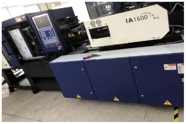
How to tell when a defect needs process adjustment — and when the mold, part design, or material condition should be reviewed
During a mold trial, it is easy to spend most of the time looking at the machine screen.
A short shot appears, so the injection pressure is increased. A burn mark appears, so the filling speed is reduced. A sink mark appears, so the holding pressure and holding time are increased.
Sometimes these adjustments are exactly what the process needs. But sometimes the defect only becomes smaller for a few cycles. Then it returns, moves to another area, or is replaced by a different problem.
That is usually the point where the team needs to stop asking "Which parameter should we change next?" and start asking "Does the mold provide the material, trapped air, heat, and molded part with a stable path?"
Process parameters are used to optimize a workable molding system. They should not be expected to compensate indefinitely for a structural limitation in the part or mold.
What Process Parameters Can Reasonably Correct
Not every molding defect requires a mold modification. Many small variations can be corrected within a normal and approved process window.
Slightly Incomplete Filling
If the part is close to full and there is no clear air trap or fixed dead corner, increasing injection pressure, adjusting filling speed, or slightly increasing melt temperature may improve flow. A process-related short shot normally responds clearly to these changes. If the unfilled area remains in exactly the same deep rib or flow-end location, however, the problem may not be pressure alone.
Mild Sink Marks
A small sink mark may improve after increasing holding pressure or extending holding time. This works when the gate remains open long enough for additional material to compensate for shrinkage. But if the sink always appears behind a thick rib, screw boss or heavy section, more packing may only transfer the problem elsewhere by creating flash or internal stress.
Light Parting-Line Flash
If flash is caused by excessive injection or holding pressure, reducing the pressure may solve it. Insufficient clamping force can also be corrected if the selected molding machine is capable of providing the required force. However, flash caused by damaged shut-offs, insufficient steel support, mold deflection, or poor parting-line fit requires a tooling review.
Surface Gloss or Exposed Glass Fiber
Mold temperature, melt temperature, and injection speed can affect surface replication and fiber appearance. For glass-filled materials, a warmer mold surface or a more suitable filling speed may allow the resin to cover the fibers more effectively. This is still a process adjustment, provided the material is correctly dried, and the gate is not creating excessive shear.
Light Ejector Whitening
Longer cooling time or slightly lower packing pressure may reduce local whitening during ejection. But if the mark always appears around the same ejector pin, rib, or high-grip area, the draft angle, surface finish, ejector contact area, and local shrinkage should also be checked.
Before Blaming the Mold, Check the Whole System
A defect should not immediately be classified as either a process problem or a mold problem. The engineer should also check material drying and contamination, resin degradation and regrind ratio, machine repeatability, hot-runner condition, cooling-water temperature and flow, part geometry and wall-thickness distribution, and differences between material batches.
Silver streaks are a good example. They may be related to trapped air, but they can also be caused by moisture, volatile contamination, material degradation, or excessive shear. A professional root-cause review starts by separating these possibilities rather than assigning every defect to one category.
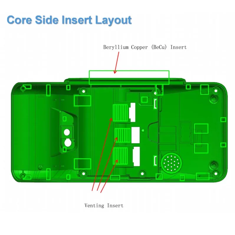
When Venting Is the Real Limitation
Air inside the cavity needs a physical path to escape. Injection pressure can compress the air, but it cannot replace a vent.
Burn Marks in a Fixed Location
If a black or brown burn mark repeatedly appears at the bottom of a deep rib, at the end of fill, or inside a closed corner, trapped gas should be investigated. Increasing injection pressure may make the problem worse — the air is compressed more rapidly, the local temperature rises, and the resin may burn through a diesel-effect condition. Reducing injection speed may reduce the burn mark, but it can also create an incomplete fill. When this happens, the process is forced to choose between two defects. The actual solution may be a venting channel, a vented insert, or a change in the local tooling structure.
Short Shot and Burn Mark in the Same Area
This combination is a strong sign of trapped air. The compressed gas blocks the incoming melt and may also burn the material. More pressure does not necessarily push the plastic farther — it may simply compress the trapped gas more severely.
Persistent Weld Lines
A weld line is influenced by melt temperature, mold temperature, flow-front temperature, and gate position. But if gas is trapped where two flow fronts meet, temperature and speed adjustments alone may not be enough. The weld-line area may need better venting, a different gate position, or a revised flow path.
Bubbles and Internal Voids Need Different Diagnoses
A gas bubble caused by trapped air is not the same as a shrinkage void inside a thick section. Trapped-air bubbles require a review of venting and flow behavior. Shrinkage voids require a review of wall thickness, gate freeze, packing transfer, and cooling. Using the same correction for both defects can waste a great deal of trial time.
When Cooling Is the Real Limitation
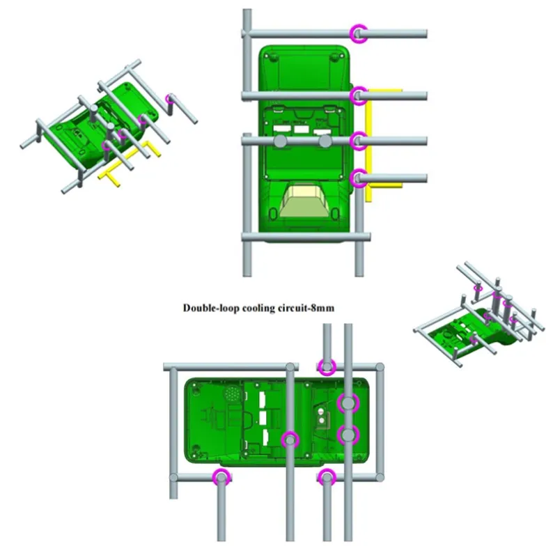
Cooling time is a parameter. Cooling layout is a mold design decision. Increasing the cooling time can allow the whole part to become colder, but it cannot remove a large temperature difference between two areas of the mold.
Warpage in a Repeatable Direction
If a part consistently bends or twists in the same direction, the cavity side, core side, or different regions of the part may be cooling at different rates. Additional cooling time may reduce the amount of deformation, but the underlying shrinkage difference can remain. The cooling circuits, local steel thickness, plastic concentration, and ejection temperature should be reviewed together.
Dimensions Drift During Continuous Production
A mold may produce acceptable parts during the first few cycles and then begin to drift as heat accumulates. The operator may repeatedly adjust holding pressure, cooling time, or mold temperature to keep the dimensions within tolerance. This is not a stable process. Cooling-water flow, blocked channels, circuit balance, and local hot spots should be checked.
Sink Marks at the Same Thick Section
Packing can improve a minor sink mark. But if the defect always appears behind the same heavy boss or rib, the section may be receiving and retaining too much heat. The product geometry may need to be reduced or cored out, and the corresponding mold area may need more effective cooling.
Cycle Time Keeps Increasing
If the cooling system cannot remove heat at the same rate that production adds it, the required cooling time gradually increases. A longer cooling setting may keep production running, but it does not improve the heat-transfer capacity of the mold.
When Gate Design Is the Real Limitation
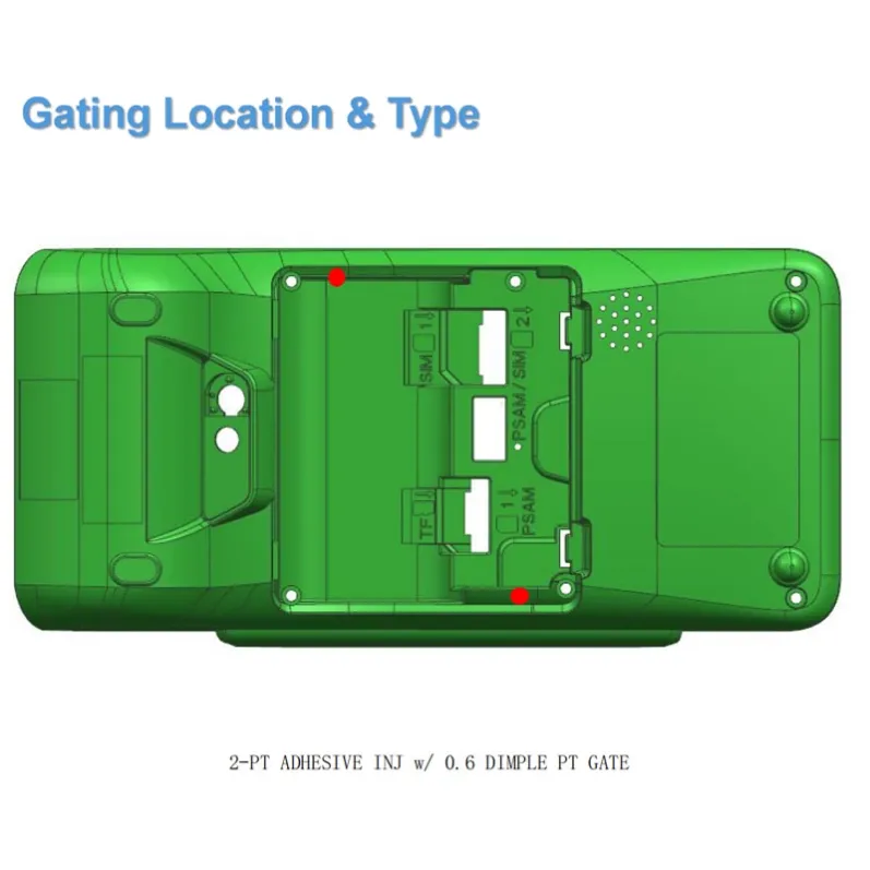
Machine parameters can change the speed and pressure of the melt. They cannot change the basic flow path created by the gate.
One Side Flashes While the Other Side Is Still Short
This usually indicates a significant filling or pressure imbalance. Increasing pressure fills the distant side but overloads the near side. Reducing pressure protects the near side but leaves the distant side incomplete. The gate location, number of gates, runner balance, or sequential-gating strategy may need to change.
Persistent Jetting
When a small gate directs a high-speed stream into a large open cavity, the melt may form a snake-like jet before contacting the cavity wall. A slower first-stage speed may help, but if the melt still enters without contacting a nearby surface, the gate direction, gate type, or local flow-control feature should be reviewed.
Shear Burning Near the Gate
A gate that is too small can create excessive shear and local heat. Reducing speed may reduce the burning but also create filling problems. The more stable correction may be to increase the gate section or modify the gate geometry.
Unstable Gate Break or Excessive Gate Vestige
If a pinpoint or submarine gate does not separate consistently, changing pressure and cooling time may provide only limited improvement. The gate size, angle, land length, and break-off structure must match the material and part geometry.
Five Practical Checks During a Mold Trial
When it is not clear whether a defect comes from the process or from a structural limitation, the Jeancen Mold engineering team normally evaluates five things.
1. Does the Defect Always Appear in the Same Location?
A defect that repeatedly appears in exactly the same feature is a strong reason to inspect the local venting, cooling, wall thickness, gate influence, and tooling structure. Location alone does not confirm the root cause, but it gives an important direction.
2. How Sensitive Is the Defect to Reasonable Parameter Changes?
A process-related problem normally responds clearly when pressure, speed, temperature or time is adjusted within the approved process window. A structural problem may improve slightly but rarely disappears completely. Sometimes one defect improves while another becomes worse.
3. Is the Problem Limited to One Cavity?
If one cavity consistently behaves differently from the others, inspect that cavity's gate, venting, cooling, steel dimensions, and surface condition. If every cavity shows the same problem, check the common process, material, hot runner, and shared mold systems first.
4. What Happens During a Continuous Run?
A stable correction should remain stable over repeated cycles. If the operator needs to keep changing the settings as production continues, heat accumulation, vent contamination, wear, or another tooling condition may be involved.
5. Can the Part Only Be Made With Abnormal Settings?
Parameters should remain within the material supplier's recommendations, machine capability, and approved process window. If the part only passes with unusually high pressure, excessive temperature, or an uneconomically long cooling time, the process is probably compensating for a deeper problem.
An Anonymized Deep-Rib Housing Case
In one electronics housing project reviewed by the Jeancen Mold engineering team, the internal geometry contained numerous thin and deep ribs. These areas created three related risks.
First, machining the entire rib region from one block of steel would be difficult. Second, air could become trapped at the ends of the deep ribs, leading to incomplete filling or burn marks. Third, the combination of deep ribs and limited draft increased the risk of sticking and uneven ejection.
Simply increasing injection pressure would not create an escape path for the trapped air. The tooling approach was therefore changed. The complex rib regions were separated into multiple precision inserts. This made the features easier to machine and allowed dedicated venting to be added directly to the insert areas. Blade ejectors were also positioned at the bottoms of the deep ribs to provide better contact and a more balanced ejection force.
The important correction was not an aggressive process setting. It was giving the trapped gas a physical path out of the cavity and giving the molded part a safer way to leave the core.
This is a useful lesson during mold trials: when a short shot and a burn mark keep returning in the same deep feature, more pressure may only change the appearance of the problem. It may not remove the cause.
A Stable Process Is More Than One Good Sample
A successful parameter adjustment brings the mold into a repeatable process window. Parameter compensation is different — compensation occurs when the operator must continually use unusual settings, extended cooling, manual trimming or repeated adjustment to keep the parts acceptable.
A few good T0 samples prove that the mold can produce the part. They do not automatically prove that the mold can repeat the result during continuous production.
Before approving a mold, the engineering team should still ask:
- Are the dimensions repeatable?
- Is the cooling condition stable?
- Does the ejection system work safely?
- Is the process window wide enough for normal production variation?
- Are any temporary adjustments hiding a structural problem?
Process parameters are essential. But the best molding process cannot replace proper venting, balanced cooling, suitable gating, safe ejection, and a moldable part design.
Sometimes the right decision is to adjust the process. Sometimes, the right decision is to stop adjusting and inspect the mold.
Related Pages
Need Help Diagnosing a Mold Trial Issue?
If your mold trial is producing defects that do not respond consistently to process adjustment, the root cause may be in the tooling, venting, cooling, or part design rather than in the process parameters.
Share your trial results, defect photos, and process data with our engineering team. We can help evaluate whether the issue requires process optimization or a tooling-level correction.