Jul 9, 2026Engineering Insights
How to Prevent Warpage in Injection Molded Parts: A Design-Stage Guide
Warpage is caused by uneven shrinkage, and it should be solved before the steel is cut. This guide covers material, structure, mold design, and simulation strategies to prevent warpage at the design
How to Prevent Warpage in Injection Molded Parts: A Design-Stage Guide
By the engineering team at Jeancen Mold
Warpage is one of the most common — and most expensive — defects in injection molding. A warped part fails inspection, won't assemble correctly, or simply looks wrong. And by the time warpage shows up on the molding floor, most of your options for fixing it cheaply are already gone.
At Jeancen, our position is simple: warpage should be solved before a single piece of steel is cut. Nearly every cause of warpage can be predicted and corrected at the design stage, where changes still cost nothing. This guide explains why parts warp, and exactly what engineers can do during design to prevent it.
What Actually Causes Warpage
Warpage has one root cause: uneven shrinkage.
As molten plastic cools from a melt to a solid, it shrinks. When different areas of a part cool and shrink by different amounts, the part develops unbalanced internal stress. That stress pulls the part out of shape — bowing, twisting, or bending it away from its intended geometry.
Everything that causes warpage traces back to this uneven shrinkage. It comes from four sources.
1. The Shrinkage Behavior of the Material Itself
Different plastics shrink by different amounts as they solidify. Filled materials — those reinforced with glass fiber, for example — shrink less than unfilled resins.
But there's a trap here that catches many engineers. Glass fiber lowers the overall shrinkage rate, but it increases anisotropy — the difference in shrinkage between the flow direction and the cross-flow direction. Polymer chains and reinforcing fibers align along the direction the melt flows, so the part shrinks differently along the flow than across it. This directional (anisotropic) shrinkage is a major and often underestimated driver of warpage, especially in glass-filled parts. Choosing a filled material to "reduce shrinkage" can actually make warpage worse if fiber orientation isn't accounted for.
2. Unsuitable Part Structure
Uneven wall thickness. Thick regions cool slowly and shrink more; thin regions cool quickly and shrink less. The mismatch creates tension inside the part that bends and twists it. This is the single most common structural cause of warpage.
Poorly designed ribs and bosses. A rib that's too thick at its base, or a boss with no radius where it meets the wall, creates a local mass of material. That mass cools slowly, shrinks more than its surroundings, and pulls distortion (or a sink mark) into the nearby surface.
Asymmetric geometry. Large unsupported flat areas, or shapes that aren't symmetrical top-to-bottom or side-to-side, cool unevenly and are far more prone to warping.
3. Mold Design Flaws
Uneven cooling. If the cooling channels don't distribute temperature evenly across the cavity, different areas of the part cool at different rates and shrink unevenly. Deep-cavity parts are especially vulnerable: if the core side is under-cooled, the difference between inner and outer cooling becomes severe.
Poor gate and runner design. A gate placed off-center, or asymmetric filling, causes uneven fill and packing pressure. Different regions end up at different densities — and different densities shrink by different amounts.
Poor ejection design. Insufficient draft angle or unevenly distributed ejector pins force the part out unevenly, physically stressing and distorting it during ejection.
4. Processing Conditions
Insufficient or excessive packing pressure, uneven mold temperature, and ejecting parts before they've fully cooled all amplify uneven shrinkage. But it's worth being honest about this: most processing problems are really design problems that weren't caught early. Process tuning can reduce warpage at the margins — it can't rescue a part whose geometry was flawed from the start.
How to Prevent Warpage at the Design Stage
Engineers have two levers to pull before tooling begins: part structure and mold design. Used well, they remove warpage at the source.
Optimizing Part Structure
Keep wall thickness uniform. This is the single most important rule for controlling warpage. Standardize the main wall thickness across the part. When a thickness change is genuinely necessary, never step abruptly from thick to thin — use a gradual transition, on the order of a 3:1 ratio over the length of the change, so shrinkage can even out.
Control ribs and bosses. Keep the base thickness of ribs at 50–60% of the main wall thickness. It's tempting to make ribs thick for strength, but a rib that's too thick becomes a slow-cooling mass that shrinks more than its surroundings and pulls a sink or warp into the surface. Add a radius to every internal corner, boss, and transition to keep wall thickness consistent and let stress flow rather than concentrate.
Design for symmetry and stiffness. Symmetrical structures cool with balanced internal stress. For large flat areas, don't just add thickness — add stiffness through flanges, ribs, or contours that work like an I-beam to resist bowing.
Select material deliberately. For parts with tight dimensional or warpage requirements, favor materials with low shrinkage and low anisotropy. If a glass-filled material is required, assess the fiber-orientation risk up front and balance it with the structural design, rather than discovering it during trials.
Optimizing Mold Design
Balance the cooling channels. Cooling should wrap the cavity evenly, keeping the moving and fixed halves at consistent temperatures. For deep-cavity parts, use baffles, spiral channels, or fountain (bubbler) cooling in the core so the core side keeps pace with the cavity side.
Optimize the gate. Place the gate on the part's neutral axis or in a thick-wall region to keep filling symmetrical. For long or large parts, use multiple gates to shorten flow length and balance packing across regions.
Standardize the ejection system. Provide adequate draft — generally at least 0.5° for smooth surfaces and at least 1° for textured surfaces. Distribute ejector pins evenly across load-bearing areas so the part isn't stressed on ejection. On deep-cavity parts, control the difference between inner and outer draft to keep wall thickness even.
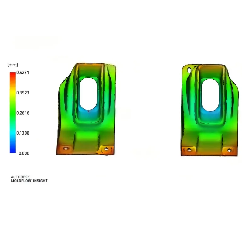
Run mold flow analysis before cutting steel. This is where design-stage prevention pays off most. Using Moldflow simulation, we model the entire filling, cooling, and shrinkage process before the mold exists — predicting where the part will warp and by how much. That lets us correct the part geometry and cooling layout while changes are still free, instead of discovering the problem during trials and re-cutting steel weeks later.
The Bottom Line
Warpage is not bad luck, and it's rarely a machine problem. It's uneven shrinkage — and uneven shrinkage is designed in or designed out long before production begins.
The engineers who consistently produce flat, dimensionally stable parts aren't the ones with the best molding machines. They're the ones who got the wall thickness, the ribs, the gates, the cooling, and the material right at the design stage — and who simulated the result before committing to steel.
That's the philosophy we build every mold around at Jeancen: engineering certainty before steel is cut. If you're facing a warpage challenge on a current or upcoming part, we're glad to review the design and run a mold flow analysis before tooling begins.