Aug 4, 2026Engineering Insights
TPU Injection Molding DFM: 9 Checks Before Tooling
Before cutting steel, review TPU grade, wall transitions, draft, texture, gating, shrinkage, cooling, venting, ejection, and overmolding interfaces.
TPU Injection Molding DFM: 9 Design Checks Before Tooling
TPU injection molding DFM is most valuable before the part design and mold concept are frozen.
A flexible part may fill successfully and still create problems during mold release, dimensional inspection, assembly, or repeated production. The review therefore needs to connect the selected TPU grade, product function, part geometry, surface requirements, mold-release strategy, and validation method.
This is not a universal rulebook for every TPU grade. Material supplier data, prototype testing, mold trials, and project-specific engineering decisions remain necessary. The purpose of this guide is to identify the questions that should be answered before detailed tooling design begins.
Why TPU Needs a Material-Specific DFM Review
TPU is a material family, not a complete molding specification.
Two TPU grades with a similar hardness can still behave differently in flow, shrinkage, surface appearance, mold release, and post-molding recovery. A hardness target alone is therefore not enough to finalize the mold allowance, gate, texture, or ejection strategy.
TPU also behaves differently from a rigid plastic during release. The finished part may stretch around a local feature, remain attached to a large mold surface, or change shape temporarily when ejector force is applied.
For these reasons, the material, geometry, surface, cooling, and ejection decisions should be reviewed as one system. Official TPU processing guidance also treats shrinkage, draft, venting, and ejection as grade- and geometry-dependent decisions rather than fixed universal values.
1. Confirm the TPU Grade and Application Requirements
Start by defining what the part must do in service.
The engineering input should include:
- Required flexibility or stiffness
- Target hardness range
- Wear, impact, chemical, UV, moisture, and temperature exposure
- Grip, sealing, cushioning, protection, or soft-contact function
- Color, gloss, texture, and cosmetic requirements
- Regulatory or application-specific requirements
- Expected production volume
- Approved material supplier and grade, if already selected
When the final grade is still open, record which tooling decisions are provisional. Shrinkage allowance, gate sizing, surface release, and dimensional validation should not be treated as final until the material direction is sufficiently clear.
A material datasheet is the starting point, not a guarantee of final molded dimensions.
2. Review Wall Thickness Together with Flow Length
Nominal wall thickness alone does not show whether a TPU part will fill and recover consistently.
The review should consider the complete flow path, including:
- Sudden thick-to-thin transitions
- Long flow into thin lips, seals, or flexible edges
- Heavy pads or local material accumulation
- Deep grooves and narrow passages
- Ribs or local reinforcement near visible surfaces
- Areas that may cool or recover at different rates
Where function allows, heavy sections can be cored out or redistributed. When a thicker section is functionally necessary, the gate, packing path, cooling, and trial plan need to account for it.
There is no single correct wall thickness for all TPU parts. The appropriate range depends on the grade, flow length, geometry, required flexibility, and production conditions.
3. Review Draft, Texture, and Mold Retention Together
Draft should not be selected independently from surface finish and ejection.
Before finalizing the part, determine:
- Which mold half should retain the part
- How much surface contact exists on each side
- Whether the part has deep walls or long draw areas
- Where texture or cosmetic finish will be applied
- Which surfaces may stretch or drag during release
- Whether ejector marks are acceptable
- Whether a stripper, sleeve, air assist, or another release method is needed
Surface finish can change TPU release behavior in either direction. A controlled rough finish may help release for some material grades, while a deep decorative texture can create additional mechanical drag. Do not assume that a smoother surface is always easier to release or that every texture needs the same draft.
Some material supplier guides recommend substantially more draft for softer grades or long draw areas than would normally be used for a rigid plastic. The final value should be based on the selected grade, texture depth, wall depth, mold finish, retention direction, and ejection method.
4. Define the Gate and Runner Strategy Before the Mold Concept Is Frozen
The gate affects more than whether the cavity can be filled.
A TPU gate review should consider:
- Total flow length
- Thin sections and local restrictions
- Fill balance
- Weld-line position
- Cosmetic and functional surfaces
- Gate vestige limits
- Pressure transmission into the end of the cavity
- Local shear and heat history
- Degating or trimming method
- Whether the runner and gate remain practical for the expected production volume
A gate that is too restrictive can increase pressure, shear, and local heat. A gate selected only for convenience may leave a visible mark, create an unfavorable weld line, or make consistent packing more difficult.
The final gate type and size should be confirmed against the actual material grade, part geometry, tool layout, and trial results. There is no universal “best gate” for all TPU components.
5. Plan Shrinkage and Dimensional Validation Together
TPU shrinkage should not be treated as one guaranteed number.
Final dimensions may be influenced by:
- Material grade and hardness
- Wall thickness
- Flow direction
- Packing conditions
- Cooling balance
- Ejection temperature
- Part geometry
- Surface condition
- Time allowed for post-molding recovery
For every fit-sensitive part, define the measurement condition before approving the tooling allowance.
The project should identify:
- Critical-to-function dimensions
- Assembly and mating dimensions
- Measurement timing after molding
- Conditioning requirements
- Inspection fixtures or support method
- Acceptable deformation during handling
- Trial dimensions that may require adjustment
A dimension measured immediately after ejection may not represent the same condition as a dimension measured after the part has cooled and recovered. Supplier data can provide an initial shrinkage direction, but trial samples remain necessary for final validation.
6. Review Cooling and Part Recovery
Cooling affects both cycle time and the condition of the part at ejection.
A TPU part released while it is still too warm may not have enough stiffness to resist ejector force or its own weight. It may stretch, twist, collapse locally, or take longer to return to its intended shape.
The cooling review should identify:
- Thick areas and local heat concentration
- Deep cores or restricted cooling locations
- Slides, inserts, or shut-offs that may retain heat
- Uneven cooling between the core and cavity sides
- Areas that need sufficient rigidity before release
- Expected part support after ejection
The objective is not simply to keep the part in the mold for as long as possible. The objective is to reach a repeatable release condition without creating an unnecessarily long cycle.
Cooling time, ejection temperature, handling, and measurement timing should therefore be included in the trial validation plan.
7. Include Venting in the Early Tooling Review
Venting should be planned before the mold layout limits where vents can be placed.
Pay particular attention to:
- End-of-fill areas
- Deep ribs, grooves, pockets, or flexible lips
- Thin flow sections
- Weld-line locations
- Insert and shut-off interfaces
- Areas where the parting line cannot provide a clear air path
- Cosmetic surfaces that may show gas-related marks
Poor venting can contribute to incomplete filling, burn marks, weak weld lines, unstable surfaces, or a narrow processing window.
However, vent depth should not be copied from an unrelated material or project. A vent that is too shallow may not remove air effectively, while an excessively deep vent may create flash. Final vent dimensions should follow the selected material supplier’s guidance and be refined during mold trials.
8. Design Ejection for Support, Not Only Force
A flexible TPU part is not automatically easy to eject.
Concentrated force from small ejector pins can create temporary deformation, permanent marks, local stretching, or push-through risk. Where geometry allows, use a larger and more balanced contact area.
The ejection review should answer:
- Where should the part remain when the mold opens?
- Which surfaces can accept ejector contact?
- Is the part sufficiently supported in the ejection direction?
- Could a lip, groove, rib, texture, or local undercut create drag?
- Would a stripper plate, ejector sleeve, larger ejector, air assist, or combined method provide better support?
- Could the part fold or collapse after leaving the tool?
- How will the part be collected and supported after ejection?
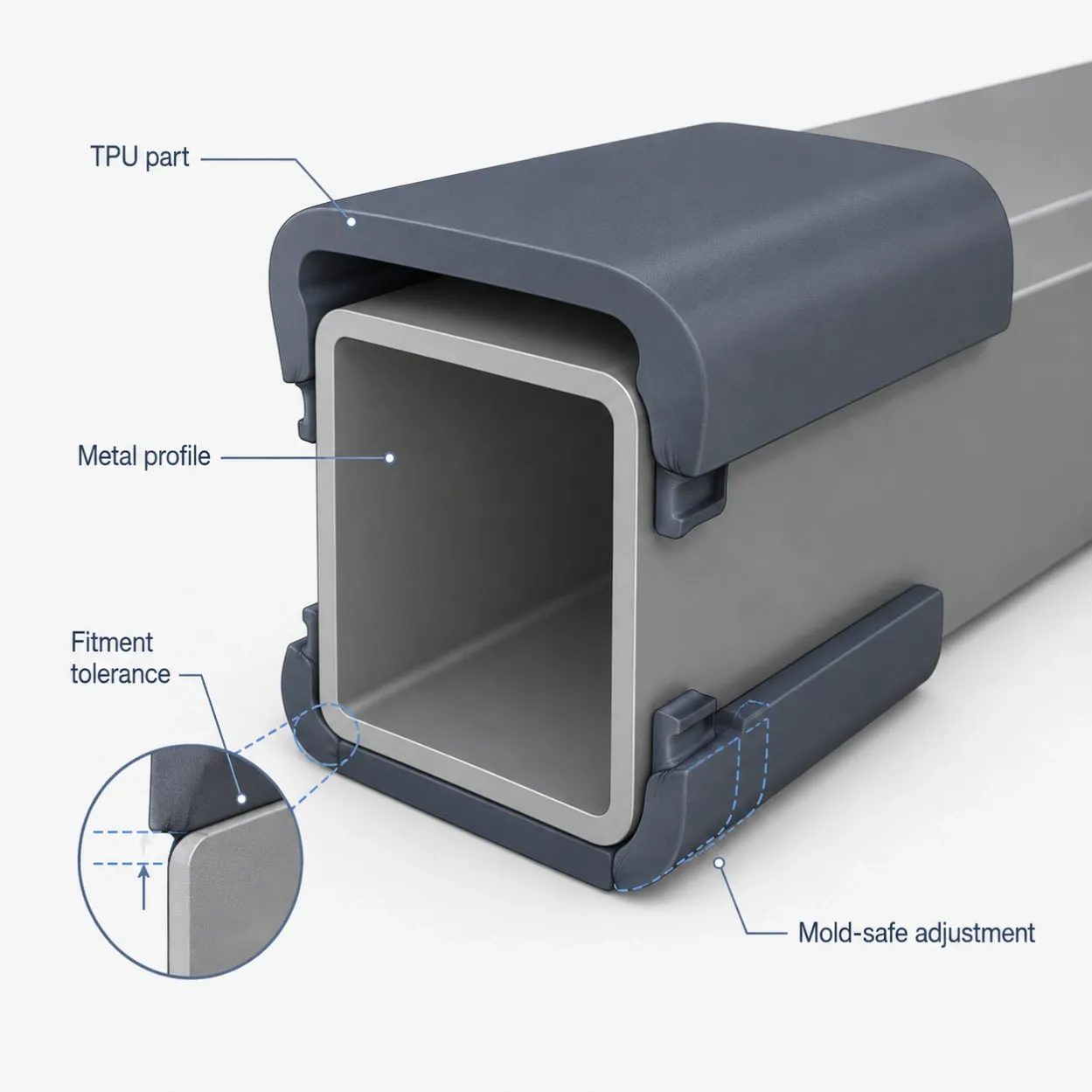
TPU elasticity may allow some undercuts to be released without a conventional slider or lifter, but flexibility alone does not prove that the design is safe. The required strain, release path, local stress, shape recovery, cosmetic effect, and repeated-cycle performance still need to be validated.
Large-area ejection is commonly recommended for TPU and other flexible elastomers because it distributes force more evenly and reduces local deformation.
9. Review Insert and Overmolding Interfaces as a Separate System
When TPU is molded onto, around, or against another component, the interface needs its own engineering review.
Confirm:
- Whether retention depends on adhesion, mechanical interlock, or both
- How the insert or substrate will be located and supported
- Whether injection pressure can move or deform it
- Surface cleanliness and preparation requirements
- Material compatibility
- Thermal expansion differences
- Shut-off and flash-control areas
- Tolerance stack-up
- Gate and flow direction around the interface
- Inspection and functional test method
Do not treat an overmolding interface as a standard TPU part with one additional feature. It can change the fill pattern, venting, mold alignment, ejection, and validation plan.
Where assembly fit is critical, provide the actual mating component or representative samples whenever possible. Nominal CAD dimensions alone may not show the full production tolerance.
Information to Prepare Before Tooling
A TPU DFM review is more useful when the following information is available:
- Current 3D model
- 2D drawing and tolerance requirements
- CAD revision status
- Product function and service environment
- TPU supplier, grade, hardness range, or required properties
- Material datasheet
- Critical dimensions and assembly requirements
- Cosmetic surfaces, texture, color, and marking requirements
- Expected annual and lifetime volume
- Mating components or assembly samples
- Insert, bonding, or overmolding requirements
- Existing prototype or test feedback
- Features that remain open for revision
Open decisions should be identified clearly rather than hidden behind assumptions.
TPU Pre-Tooling Release Checklist
Before releasing the detailed mold design, confirm that:
- The material grade or grade-selection process is defined
- Functional hardness and service conditions are recorded
- Wall transitions and flow restrictions have been reviewed
- Draft, texture, retention, and ejection are compatible
- Gate restrictions and cosmetic requirements are clear
- Critical dimensions and measurement timing are defined
- Shrinkage allowance is treated as a trial-validated value
- Cooling and part recovery have been considered
- End-of-fill areas and venting routes are identified
- Ejection force is distributed over suitable contact areas
- Undercuts have been checked for strain and shape recovery
- Insert or overmolding interfaces have a separate validation plan
- Open product decisions are documented before tooling release
Frequently Asked Questions
Can TPU DFM begin before the final CAD is complete?
Yes. A preliminary review can begin from partial CAD, drawings, samples, or functional requirements. The purpose is to identify decisions that must be completed before the mold concept and detailed tooling design are released.
Is there one standard draft angle for TPU?
No. Draft depends on the grade, hardness, wall depth, surface finish, texture, shrinkage, retention direction, and ejection method. Softer grades and long draw areas may require more draft than rigid plastic parts.
Can the mold shrinkage allowance be fixed before the TPU grade is selected?
Only as a preliminary assumption. The final allowance should be checked against the selected grade, geometry, flow direction, molding conditions, and trial measurements.
Is a flexible TPU part easier to eject?
Not necessarily. Flexibility may help a part pass over some features, but it can also cause stretching, drag, collapse, or uneven deformation. The release path and ejection support still need to be engineered.
Can one mold run several TPU grades without changes?
Possibly, but it should not be assumed. A different grade may change flow, shrinkage, surface appearance, release behavior, processing window, and final dimensions. Each alternative grade should be revalidated.
Need TPU Tooling or Production Support?
This guide covers the engineering questions that should be resolved before tooling. For commercial information about DFM support, mold manufacturing, trials, and custom TPU molded parts production, see our TPU Molded Parts and Tooling Support page.
Jeancen Mold supports overseas product teams with early manufacturability review, tooling development, trial validation, and injection molding production.