Jul 30, 2026Engineering Insights
8 Critical DFM Rules for Injection Molding Before Tooling Starts
A plastic part can look perfect in CAD and still create serious problems during injection molding. This is one of the most common risks in new product development. A design may meet the visual target,
A plastic part can look perfect in CAD and still create serious problems during injection molding.
This is one of the most common risks in new product development. A design may meet the visual target, assembly concept, or industrial design intent, but still be difficult, expensive, or unstable to mold.
At Jeancen Mold, we often review projects where the main tooling risks are already built into the part design before steel is cut. Uneven wall thickness, sharp internal corners, insufficient draft, hidden undercuts, weak rib design, or unrealistic surface texture requirements can all lead to sink marks, warpage, short shots, ejection issues, longer cycle times, and repeated tooling modifications.
That is why DFM should not be treated as a final check after the design is “almost finished.” It should be part of the engineering decision-making process before mold manufacturing begins.
Below are eight practical DFM rules that product developers, engineers, and sourcing teams should review before starting an injection mold project.
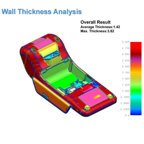
1. Keep Wall Thickness as Uniform as Possible
Wall thickness is one of the first areas we check during an injection molding DFM review.
When one area of the part is much thicker than another, the plastic does not cool evenly. Thicker sections cool more slowly, which can create sink marks, internal stress, shrinkage variation, and warpage.
A common mistake is adding material to make a part “stronger.” In many cases, this does not improve the part. It simply creates more molding risk.
A better solution is to maintain a more uniform wall thickness and use ribs, gussets, or structural geometry to improve strength without adding unnecessary bulk.
For appearance-critical housings, tight-tolerance parts, and functional assemblies, wall thickness control is especially important because small shrinkage differences can affect both cosmetic quality and fit.
2. Use Ribs for Strength, Not Excessive Thickness
Ribs are often a better way to improve stiffness than making the entire part thicker.
However, rib design also needs control. If ribs are too thick, they can cause sink marks on the opposite cosmetic surface. If ribs are too tall or too thin, they may create filling difficulty, weak steel conditions, or ejection problems.
As a general DFM principle, ribs should be designed with proper thickness, draft, radius, and spacing. The goal is to support function without creating molding defects.
For parts such as electrical housings, connector housings, relay housings, and structural covers, rib strategy often affects both part strength and long-term dimensional stability.
3. Add Enough Draft for Reliable Ejection
Draft angle is often underestimated during early product design.
Without enough draft, the molded part may stick to the core or cavity. This can lead to drag marks, deformation, unstable ejection, cosmetic defects, and longer cycle times.
Draft becomes even more important when the part has:
- Deep walls
- Textured surfaces
- Tall ribs
- Internal bosses
- Tight cosmetic requirements
- Soft materials such as TPU
- Large contact areas with the mold steel
Surface texture also changes the draft requirement. A smooth surface may release more easily, while a textured surface usually needs additional draft to prevent scuffing or dragging during ejection.
For cosmetic or appearance-critical parts, draft is not only a tooling issue. It directly affects the final visible quality of the molded component.
4. Avoid Undercuts Unless They Are Truly Necessary
An undercut is any feature that prevents the part from being ejected directly from the mold.
Undercuts often require sliders, lifters, collapsible cores, or other moving mold mechanisms. These features can be necessary, but they also increase tooling complexity, cost, maintenance risk, and mold trial uncertainty.
The best undercut is the one that can be removed by smart part design.
Before accepting an undercut, the design team should ask:
- Can the feature be moved to the parting direction?
- Can the clip or snap-fit be redesigned?
- Can the geometry be opened to avoid side action?
- Will this undercut create weak steel or maintenance problems?
- Is the function worth the added mold complexity?
For high-volume production, even a small undercut can become expensive if it causes wear, sticking, frequent adjustment, or unstable ejection.
5. Design Holes, Bosses, and Core Pins Carefully
Holes and bosses look simple in CAD, but they can create real tooling risks.
Small deep holes often require thin core pins. These pins may be difficult to cool, difficult to support, and more likely to break during production. In multi-cavity molds, this risk becomes even more important because one broken core pin can stop the whole tool.
Bosses also need careful review. If the wall around a boss is too thick, sink marks may appear on the opposite surface. If the boss is too tall or poorly supported, it may deform or create filling problems.
A good DFM review should check:
- Hole depth-to-diameter ratio
- Core pin strength
- Boss wall thickness
- Rib support around bosses
- Cooling around thick features
- Ejection force near bosses and holes
This is especially important for electrical components, connector housings, and precision functional parts where holes and bosses often control assembly accuracy.
6. Use Proper Radii Instead of Sharp Corners
Sharp internal corners increase stress concentration and make plastic flow less smoothly.
In molded plastic parts, proper radii help improve material flow, reduce stress, improve mold filling, and support better long-term part performance. They also reduce the risk of weak steel conditions in the mold.
A common issue is using sharp corners in structural areas, snap-fit features, or internal transitions. These areas may look clean in CAD, but they can create cracks, stress whitening, filling hesitation, or tool manufacturing difficulty.
DFM review should check both external and internal radii, especially around:
- Ribs
- Bosses
- Snap-fit features
- Corners near thick-to-thin transitions
- Structural load areas
- Cosmetic edges
For parts that need long-term field performance, radii are not just a cosmetic decision. They are part of the mechanical design strategy.
7. Match Material Selection with Shrinkage and Application Requirements
Material selection directly affects mold design.
ABS, PC, PMMA, PA66, PBT, TPU, PP, and glass-filled materials all behave differently during molding. They have different shrinkage rates, flow characteristics, cooling behavior, moisture sensitivity, strength, surface requirements, and dimensional stability.
If material selection is changed late in the project, the mold design may also need to change.
For example:
- PC often needs careful control of venting, polishing, and stress.
- PMMA requires attention to optical clarity and surface defects.
- PA66+GF needs consideration of fiber orientation, wear, and dimensional stability.
- TPU requires careful ejection strategy to avoid deformation.
- PP may require more attention to shrinkage and warpage control.
This is why material choice should be reviewed before tooling starts, not after the mold is already being built.
8. Review Parting Line, Gate, Ejection, and Cooling Early
DFM is not only about the plastic part. It is also about how the part will be molded.
Before tooling begins, the team should review the basic mold strategy:
- Where should the parting line be?
- Where should the gate be placed?
- Will the gate affect appearance or function?
- How will the part be ejected?
- Are ejector marks acceptable in those locations?
- Can the mold be cooled effectively?
- Will the cooling design support stable cycle time?
- Are there risks of warpage, weld lines, air traps, or short shots?
These decisions influence part quality, mold cost, tooling lead time, cycle time, and long-term production stability.
For NPI projects, early review of gate, cooling, ejection, and parting line strategy can prevent expensive changes after the first trial.
Why DFM Should Happen Before Steel Is Cut
Many tooling problems are not caused by poor machining or poor molding operation. They are caused by design risks that were not reviewed early enough.
Once steel is cut, every design correction becomes more expensive.
A proactive DFM review can help identify:
- Sink mark risks
- Warpage risks
- Weak steel conditions
- Ejection problems
- Cooling limitations
- Gate and weld line concerns
- Assembly tolerance issues
- Material and shrinkage mismatch
- Unnecessary tooling complexity
For buyers, this does not only reduce technical risk. It also helps control total tooling cost, reduce trial loops, and improve project predictability.
Jeancen’s Approach to DFM Review
At Jeancen Mold, we use DFM as a front-loaded engineering step before mold manufacturing begins.
Our review focuses on practical tooling and production risks, including part geometry, wall thickness, material behavior, mold structure, gate position, cooling strategy, ejection method, and long-term maintenance.
This is especially important for projects involving:
- High-precision molded parts
- Appearance-critical components
- Electrical and electronic housings
- Insert-molded parts
- TPU molded parts
- Optical PMMA or PC parts
- Prototype-to-production tooling
- Multi-cavity or family mold projects
The goal is not simply to point out problems. The goal is to help the customer make better engineering decisions before the project moves too far.
Need a DFM Review Before Tooling?
If you have a 3D file, drawing, sample part, or early product concept, Jeancen Mold can help review the main injection molding risks before tooling starts.
You can send your project information to:
info@jeancen.com
For early-stage projects, we can help check part geometry, material selection, moldability risks, gate and ejection strategy, and potential tooling cost drivers before steel is cut.
A short DFM review at the beginning can prevent expensive corrections later.