Jul 13, 2026Technical Case Studies
Controlling Warpage Before Steel Cutting: An Anonymized Plastic Housing DFM Case
A PC/ABS housing DFM case showing why wall thickness, cooling, ribs, gate position, and ejection must be reviewed as one system to control warpage before steel cutting.
Why wall thickness, cooling, ribs, and ejection must be reviewed as one system
A plastic housing can look completely acceptable in CAD and still develop warpage after molding.
In many projects, warpage is not caused by one obvious mistake. It is usually the combined result of several small design and tooling decisions: uneven wall thickness, different cooling rates, unbalanced filling pressure, local shrinkage, and uneven ejection force.
This case is based on an actual plastic housing DFM review completed by the Jeancen Mold engineering team. The customer name and product application are not shown, but the engineering issues and review process are kept as they appeared during the project.
The Initial Part Condition
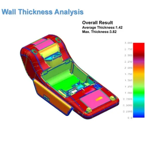
The part was a relatively large electronic housing made from PC/ABS. Its average wall thickness was approximately 1.42 mm, but some local areas reached around 3.82 mm. At the same time, one narrow section was only about 0.62 mm thick.
This created two opposite risks in the same part. The thin area could cause incomplete filling or a narrow process window. The thick areas could cool and shrink more slowly, increasing the possibility of sink marks, internal stress, and dimensional movement after ejection.
Several ribs were also thicker than 60% of the surrounding main wall. Individually, none of these details looked especially serious. But when they appeared together in one housing, the risk of uneven shrinkage and warpage became much higher.
Warpage Is Not Only a Cooling Problem
When a molded housing bends or twists, cooling is often blamed first. Cooling is important, but it is only one part of the problem. In this project, the engineering team reviewed several areas together.
Wall Thickness Distribution
The first step was to identify abrupt wall thickness changes. A thick section not only takes longer to cool, but it also receives and retains more packing pressure than a nearby thin section. This creates different shrinkage conditions within the same part.
Where possible, the wall transition should be made more gradual. Where the structure cannot be changed, the mold and process strategy must account for the difference.
Rib and Boss Geometry
Ribs improve stiffness, but a rib that is too thick can create a new shrinkage problem. The area behind the rib may cool slowly and pull the surrounding surface inward. For a cosmetic housing, this may appear as a sink mark. For functional housing, it may contribute to local distortion and assembly mismatch.
The review therefore, considered rib thickness together with the main wall, rather than treating the rib as an independent feature.
Filling Direction and Gate Position
The gate does more than bring plastic into the cavity. It also determines the filling direction, pressure distribution, and molecular orientation inside the part.
If one side fills and packs much earlier than the other, the final shrinkage may not be symmetrical. This is why gate location should be reviewed together with the part shape and expected deformation direction. A gate that fills the part successfully is not automatically the best gate for dimensional stability.
Cooling Balance
The cavity and core sides of a housing often have very different geometries. One side may be relatively smooth, while the other contains ribs, bosses, inserts, lifters, and deep features. Using a simple cooling layout without considering these differences can leave local hot areas inside the mold.
For this project, the cooling review focused on the areas with greater steel depth and higher plastic concentration. The goal was not simply to reduce the average cycle time. The more important goal was to make different areas of the part reach a similar ejection condition.
Ejection and Lifter Clearance
Warpage can also be introduced during ejection. If the part is still hot and one area receives more ejector force than another, the housing may deform as it leaves the core. Ribs located behind a lifter also require sufficient clearance — without it, the lifter may scrape or drag the part during movement.
For this reason, the ejector layout, lifter movement, and part stiffness were reviewed together.
Why the Team Did Not Start by Adjusting Process Parameters
Injection speed, holding pressure, mold temperature, and cooling time can all influence warpage. But these settings should not be used to hide a structural problem.
A process engineer may temporarily reduce deformation by increasing cooling time or changing packing pressure. However, if the mold still contains an unbalanced cooling layout or the part still has severe wall thickness variation, the process window may remain narrow. The part may look acceptable during one trial and then move again when the material batch, room temperature, or production cycle changes.
The Jeancen approach was to first identify which risks came from the product design and which came from the tooling concept. Only after those areas were reviewed would the process settings be used for final optimization.
For a deeper explanation of warpage causes and design-stage prevention strategies, see our related guide: How to Prevent Warpage in Injection Molded Parts: A Design-Stage Guide
T0 Is a Verification Stage, Not the End of the Project
The first trial brings the product design, mold steel, plastic material, and molding process together for the first time. A few acceptable samples do not automatically prove production stability.
For a housing with possible warpage risk, the trial review should include:
- Dimensional consistency over repeated cycles
- Cooling balance between different regions
- Assembly fit after the part has fully conditioned
- Ejection stability
- Sensitivity to holding pressure and mold temperature
- Whether any manual correction is hiding the real condition
The objective is not only to produce one good sample. The objective is to establish a repeatable molding condition that can remain stable during production.
Engineering Takeaway
Warpage prevention rarely comes from one single correction. It normally requires the product and mold to be reviewed as a complete system.
Wall thickness affects shrinkage. Ribs affect stiffness and local cooling. Gate position affects filling and pressure orientation. Cooling affects the temperature difference across the part. Ejection determines whether the part keeps its shape when it leaves the mold.
When these decisions are reviewed before steel cutting, the team has more options and the corrections are usually smaller. After T0, the same correction may require welding, remachining, new inserts, or a much narrower process window.
That is why practical DFM should not only ask: "Can this part be molded?"
It should also ask: "Can this part be molded repeatedly, stay within tolerance, and assemble correctly during production?"
Related Pages
Need Help with a Warpage-Sensitive Housing Project?
If you are developing a plastic housing where dimensional stability, assembly fit, or cosmetic flatness are critical, our engineering team can help review the warpage risk before steel is cut.
Share your 3D file, material information, and dimensional requirements. We can evaluate wall thickness distribution, cooling logic, rib design, and gate strategy as a system — not as isolated checklist items.