Jul 30, 2026Technical Case Studies
Case Study: Solving Metal Insert Shift and Warpage in an Automotive Insert Molding Project
Insert molding looks simple when viewed from the finished part. A metal insert is placed into the mold, plastic is injected around it, and the final component combines the strength or function of meta
Insert molding looks simple when viewed from the finished part.
A metal insert is placed into the mold, plastic is injected around it, and the final component combines the strength or function of metal with the design flexibility of plastic.
But in real production, insert molding can create serious quality risks if the insert is not positioned, retained, and protected correctly during injection.
This automotive project was a clear example.
The customer came to Jeancen Mold after several previous mold suppliers failed to deliver acceptable quality. The main issue was a thin stamped metal insert that kept shifting during injection molding. Under high injection pressure, the insert moved from its intended position, creating unstable dimensions and a high defect rate.
The visible problem was insert shift.
The deeper problem was that the mold design did not properly control insert positioning, plastic flow, cooling, gas venting, and ejection force as one complete system.
At Jeancen Mold, we treated this project as an engineering risk-control case, not just a mold build.
Project Overview
Item | Detail |
|---|---|
Project Type | Automotive insert molding |
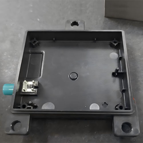
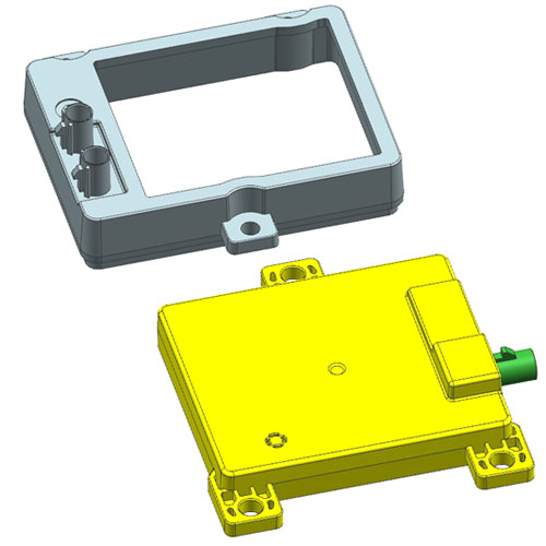
Part Type | Frame housing / enclosure component |
Main Insert | Thin stamped metal insert |
Previous Issue | Insert shift during molding |
Reported Defect Rate | Over 40% before redesign |
Key Risks | Insert movement, sink marks, gas traps, warpage, ejector marks |
Jeancen Solution | Dual positioning, retention design, DFM optimization, moldflow review, cooling control, balanced ejection |
Result | 98.5% first-article approval rate, defect rate below 0.3%, full production within 45 days |
This project required more than placing a metal insert inside a mold.
The insert had to remain stable under injection pressure, the plastic had to fill around complex ribs and bosses, the flat surface had to remain controlled during cooling, and the finished part had to release without deformation or visible ejector damage.
The Core Problem: Metal Insert Shift During Injection
The main failure from previous attempts was insert movement.
During injection molding, molten plastic enters the cavity under high pressure. In this project, the injection pressure exceeded 50 MPa. That pressure was enough to displace the thin stamped metal insert if the insert was not properly supported.
Once the insert shifted, several downstream problems occurred:
- Incorrect insert position
- Unstable assembly dimensions
- Poor functional fit
- Increased scrap rate
- Inconsistent part quality
- Customer rejection during inspection
For insert molding, positioning accuracy is not only a mold setup issue. It must be designed into the mold structure.
The insert needs to be located, retained, and protected throughout the injection cycle.
Jeancen’s Solution: Dual-Positioning and Insert Retention Design
To control insert shift, Jeancen designed a dual-positioning system.
The solution included:
- Precision locating pins
- Strategic insert retention features
- Controlled contact points
- Stable insert seating before mold close
- Support against plastic flow pressure
- Mold structure review to avoid insert floating or tilting
The goal was to prevent movement in all critical directions during injection.
A common mistake in insert molding is to assume that placing the insert into a cavity pocket is enough. It is not.
The insert must remain stable during:
- Loading
- Mold closing
- Injection pressure
- Packing pressure
- Cooling shrinkage
- Mold opening
- Part ejection
By reviewing the full molding sequence, Jeancen improved insert positioning stability and achieved insert position accuracy within 0.05 mm.
Challenge 2: Sink Marks and Gas Traps Around Ribs and Bosses
The part also included deep ribs and bosses.
These features were necessary for structure and assembly, but they created molding risks.
If ribs are too thick, they can create sink marks on the visible surface. If deep ribs or bosses are not properly vented, trapped air can cause short shots, burn marks, weak filling, or surface defects.
In this project, the previous mold attempts had struggled with visible defects and incomplete filling around complex internal features.
The part was not simply an insert molding challenge. It was also a DFM challenge.
Jeancen’s Solution: Rib Optimization and Micro-Venting
Jeancen reviewed the rib and boss design during the DFM stage.
The optimization included:
- Rib thickness control at approximately 40–60% of the main wall thickness
- Review of thick-to-thin transitions
- Independent inserts in difficult internal zones
- Micro-venting channels at critical gas trap locations
- Filling path review to reduce short shot risk
- Mold structure adjustment around deep rib areas
The purpose was to improve both appearance quality and filling reliability.
Instead of trying to fix sink marks or gas traps only through molding parameters, Jeancen addressed the root causes in part design and mold structure.
The result was complete cavity filling and no visible sink marks in the critical areas.
Challenge 3: Warpage on Large Flat Surfaces
Large flat surfaces are difficult to control in injection molding.
When cooling is uneven, plastic shrinkage becomes unbalanced. This can cause warpage, twisting, or poor flatness.
In this project, the enclosure frame had flat surface areas that were sensitive to cooling imbalance.
The risk was especially high because the part also included:
- Metal insert areas
- Ribs and bosses
- Thick and thin sections
- Complex internal geometry
- Local heat concentration zones
These features can all influence shrinkage and part deformation.
If cooling is not properly controlled, the part may look acceptable immediately after molding but fail dimensional inspection or assembly later.
Jeancen’s Solution: Moldflow Review, Cooling Optimization, and BeCu Inserts
Jeancen used moldflow analysis and cooling review to identify hot spots and warpage risk areas.
The mold design was then optimized through:
- Improved cooling circuit layout
- Localized thermal balance review
- Beryllium copper inserts at heat concentration zones
- Mold temperature control strategy
- Review of packing and shrinkage behavior
- Flatness risk evaluation before tooling finalization
Beryllium copper inserts were used selectively, not everywhere.
The purpose was to improve local heat dissipation where standard steel cooling could not sufficiently remove heat.
This helped reduce thermal imbalance and supported better flatness control across the molded part.
The project achieved flatness within 0.15 mm across the main surface.
Related article: Why Beryllium Copper Inserts Are Used for Heat Dissipation in Injection Molds
Challenge 4: Balanced Ejection Without Deformation
The final major risk was ejection.
The part contained complex internal geometry, ribs, bosses, metal insert areas, and flat surfaces. If ejection force was not distributed correctly, the part could deform, mark, or stick during release.
In insert molding, ejection strategy must also consider the interaction between plastic shrinkage and the metal insert.
Poor ejection can cause:
- Ejector marks
- Local deformation
- Stress around insert areas
- Part sticking
- Dimensional change after demolding
- Surface damage
The solution had to release the part cleanly without damaging cosmetic or functional areas.
Jeancen’s Solution: Multi-Point Ejection System
Jeancen designed a balanced multi-point ejection system using a combination of ejector types.
The ejection strategy included:
- Ejector pins
- Ejector sleeves
- Blade ejectors
- Force distribution across stronger structural areas
- Avoidance of sensitive cosmetic or functional zones
- Support around deep internal features
- Controlled release sequence to reduce deformation risk
The goal was to distribute ejection force rather than concentrate it in weak areas.
This helped avoid visible ejector marks and prevented deformation during part release.
Why Previous Suppliers Failed
This project was not failed by one single problem.
It failed because several risks were interacting:
- The insert shifted under injection pressure.
- Ribs and bosses created sink mark and gas trap risks.
- Flat surfaces were sensitive to cooling imbalance.
- Ejection force could deform the part.
- The mold design did not fully control the process sequence.
In complex insert molding, solving one issue while ignoring the others is not enough.
A stable result requires the moldmaker to review insert placement, flow behavior, venting, cooling, shrinkage, ejection, and inspection together.
This is where experienced DFM and tooling design become critical.
Final Results
After redesigning the insert positioning, venting, cooling, and ejection strategy, the project achieved stable results.
Key outcomes included:
- Insert position accuracy within 0.05 mm
- Flatness controlled within 0.15 mm
- No visible sink marks in critical areas
- Complete cavity filling
- No ejector marks
- No deformation during release
- 98.5% first-article approval rate
- Defect rate reduced below 0.3%
- Full production achieved within 45 days
For the customer, this meant the project could move forward after several failed supplier attempts.
For Jeancen, the result demonstrated the value of front-loaded engineering risk control in insert molding.
What Buyers Should Learn from This Case
Insert molding projects should not be treated as standard injection molding projects with a metal piece added.
The insert changes the entire molding risk profile.
Before starting an insert molding project, buyers should confirm:
- How the insert will be located
- How insert movement will be prevented
- Whether the insert can withstand injection and packing pressure
- Where gas traps may form
- Whether ribs and bosses create sink mark risk
- How cooling will control warpage
- Whether local heat concentration needs special treatment
- How the part will be ejected without deformation
- How insert position will be inspected
- What tolerance is required for functional assembly
These questions should be answered before steel is cut.
Why This Case Matters for Automotive Insert Molding
Automotive insert molded parts often carry strict requirements for fit, strength, assembly, and long-term stability.
A small insert shift can create major downstream problems.
For example:
- Assembly failure
- Electrical contact issues
- Functional misalignment
- Poor sealing
- Customer rejection
- High scrap rate
- Field reliability concerns
This is why insert molding must be engineered around repeatability.
The right mold design does not only hold the insert. It controls the full molding system.
Need Help with an Insert Molding Project?
Jeancen Mold supports insert molding, metal insert overmolding, DFM review, mold design, moldflow analysis, tooling manufacturing, validation, and pilot production for automotive, electrical, electronic, industrial, and functional molded components.
If your project involves metal insert shift, warpage, sink marks, gas traps, tight assembly tolerance, or previous tooling failure, we can help review the main mold risks before steel is cut.
Send your drawings, 3D files, or current tooling concerns to:
info@jeancen.com
Jeancen Mold helps buyers reduce insert molding uncertainty before tooling begins — through practical DFM review, precision insert positioning, and production-focused mold engineering.