Jul 30, 2026Technical Case Studies
Case Study: Solving Automotive Housing Assembly Fit Issues with GOM 3D Scanning
In precision injection molding, a part can pass standard dimensional checks and still fail during assembly. This is one of the most frustrating problems for automotive projects. The T1 samples may loo
In precision injection molding, a part can pass standard dimensional checks and still fail during assembly.
This is one of the most frustrating problems for automotive projects.
The T1 samples may look correct. The key dimensions may measure within tolerance using calipers or selected CMM points. But when the parts are assembled on the production line, the real problem appears: uneven gaps, poor mating fit, failed clips, local interference, or unstable assembly feel.
This was exactly the challenge in one automotive housing project reviewed by Jeancen Mold.
The customer reported poor assembly fit during the trial stage. Traditional point-based measurements did not clearly identify the root cause. The part was not obviously defective by visual inspection, and several key dimensions appeared acceptable.
The question was:
Was the problem caused by warpage, shrinkage, hidden interference, or a local profile deviation?
To avoid guessing, Jeancen used GOM ATOS Core 3D blue light scanning to inspect the full part surface and diagnose the actual deformation pattern.
Project Overview
Item | Detail |
|---|---|
Project Type | Automotive housing dimensional diagnosis |
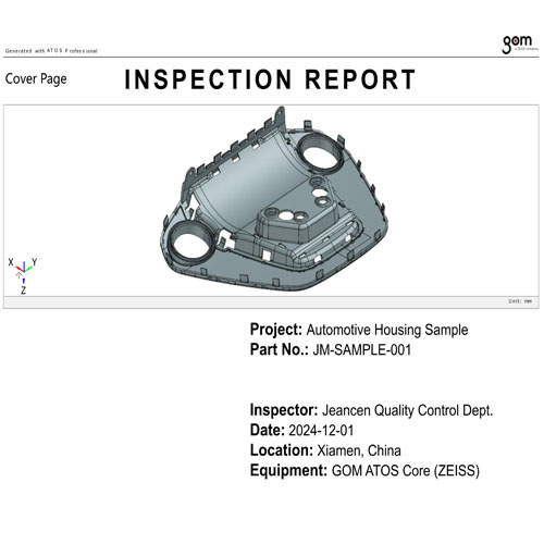
Part | Automotive housing sample |
Main Issue | Poor assembly fit after T1 trial |
Inspection Method | GOM ATOS Core 3D blue light scanning |
Main Finding | Hidden profile deviation on curved surface |
Engineering Action | Steel-safe mold correction guided by scan data |
Final Goal | Restore assembly fit and dimensional stability |
This was not a routine inspection case.
It was an engineering troubleshooting case where conventional measurement could not fully explain the assembly problem.
The value of GOM scanning was not only to generate a report. The value was to convert an unclear assembly failure into visible, measurable, full-surface data.
The Challenge: When Calipers and CMM Points Are Not Enough
For many injection molded parts, standard inspection methods are useful.
Calipers can check simple dimensions. CMM can measure selected points. Fixtures can check critical assembly positions.
But complex automotive housings often contain curved surfaces, flexible edges, ribs, bosses, clips, and mating geometry. A local deformation in one curved area may not be captured by a few selected measurement points.
This creates a common problem:
- The part appears acceptable visually.
- Several key dimensions are within tolerance.
- The assembly still fails.
- The root cause is unclear.
- Mold modification becomes risky because the team does not know where to correct.
If the supplier guesses wrong, the mold may be modified in the wrong area, creating new problems instead of solving the original one.
For this project, Jeancen needed a more complete diagnostic method.
Why Assembly Fit Problems Are Difficult to Diagnose
Automotive housing fit issues often come from combined causes.
Possible causes include:
- Local warpage
- Uneven shrinkage
- Cooling imbalance
- Material orientation
- Gate or packing imbalance
- Ejection stress
- Hidden interference
- Profile deviation on a curved surface
- Mold steel condition mismatch
- Incorrect compensation during earlier modification
The difficulty is that these problems do not always show up as simple length, width, or hole-position errors.
A part can be “dimensionally acceptable” at selected inspection points but still fail because the full surface shape has shifted.
This is why full-field inspection becomes valuable for troubleshooting.
Jeancen’s Diagnostic Method: GOM ATOS 3D Scanning
At Jeancen Mold, we use GOM 3D scanning as a high-level diagnostic tool for complex dimensional problems.
In this project, our quality and engineering team used GOM ATOS Core, a ZEISS 3D blue light scanning system, to create a digital comparison between the physical molded part and the CAD data.
Unlike traditional point-based inspection, 3D scanning captures the full surface behavior of the part.
This allows engineers to see:
- Where the part matches CAD
- Where the part deviates from CAD
- Whether the deviation is local or global
- Whether deformation is related to warpage or shrinkage
- Whether the assembly problem comes from a hidden surface profile issue
- Which mold areas may need steel-safe correction
The result is not just a measurement. It is a visual engineering map.
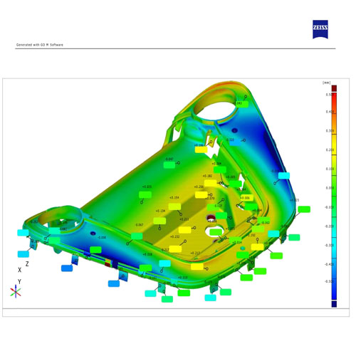
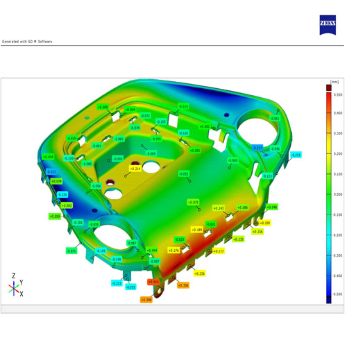
The Diagnosis: Color Deviation Analysis
After scanning the automotive housing sample, the GOM software generated a color deviation map.
This heat map immediately revealed what traditional inspection had missed.
While several key dimensions appeared acceptable, the full-surface scan showed a profile deviation in a curved region of the housing. This local deformation was not obvious to the naked eye, but it directly affected assembly fit.
The color deviation map helped the team identify:
- The exact area of deformation
- The direction of deviation
- The magnitude of the profile error
- The relationship between local surface shift and assembly failure
- The mold correction zone
This changed the troubleshooting process from opinion-based discussion to data-based correction.
Instead of asking, “Where do we think the problem is?” the team could now ask:
Which exact surface area does the scan data tell us to correct?
Why Full-Surface Data Matters
A complex molded housing is not only defined by several points.
Its assembly behavior depends on the full 3D shape.
When a part mates with another component, contact may occur along surfaces, edges, ribs, clips, curved areas, or local support features. If one of these surfaces is slightly deformed, the part may fail assembly even when basic dimensions look acceptable.
GOM scanning helps reveal these hidden issues because it captures the entire surface.
For assembly troubleshooting, this provides several advantages:
- Faster root-cause identification
- Less reliance on trial-and-error
- Better mold correction decisions
- Clearer communication between quality and tooling teams
- Visual evidence for customer review
- Reduced risk of modifying the wrong mold area
For automotive projects with strict launch schedules, this can directly protect time-to-market.
The Engineering Fix Strategy
Finding the deviation was only the first step.
The next step was to translate the scan data into a mold correction plan.
Jeancen’s engineering team followed a controlled correction process.
Step 1: Lock the Stable Molding Parameters
Before modifying the mold, the team first confirmed stable production parameters.
This is important because if the process is unstable, the scan result may reflect process variation rather than mold steel condition.
Key process factors reviewed included:
- Mold temperature
- Melt temperature
- Injection speed
- Packing pressure
- Cooling time
- Part ejection condition
- Material drying and handling
- Repeatability of sample production
The purpose was to ensure that the dimensional deviation was repeatable and meaningful.
Only after confirming process stability should mold steel correction begin.
Step 2: Use Scan Data as the Correction Roadmap
The GOM deviation map was then used as a roadmap for steel-safe mold modification.
Instead of making broad or uncertain corrections, the team focused on the deviation zones identified by the scan.
This helped guide decisions such as:
- Where to add steel-safe compensation
- Where to remove or adjust mold material
- How much correction was needed
- Which areas should remain untouched
- How to avoid creating new assembly or surface defects
This is the key benefit of 3D scanning in mold correction.
The scan does not replace mold engineering experience. It gives the engineering team a more accurate foundation for making correction decisions.
Steel-Safe Mold Correction
For precision injection molds, correction strategy must be conservative and controlled.
A moldmaker should not rush into aggressive steel removal without understanding the full dimensional impact.
In this case, the correction was made using a steel-safe approach.
The team reviewed:
- Scan deviation direction
- Mold core and cavity relationship
- Shrinkage compensation logic
- Assembly interference zone
- Local part thickness and stiffness
- Risk of over-correction
- Effect on mating surfaces
The correction plan was then executed in the mold area linked to the assembly problem.
The goal was not only to bring the part back into dimensional tolerance. The goal was to restore functional assembly fit.
Verification After Mold Modification
After mold correction, new samples were produced and scanned again.
This second scan verified whether the correction had improved the deviation pattern and whether the part was now closer to the CAD target.
The final samples brought the critical deviation back into the required tolerance range, and the assembly fit was confirmed on the production line.
The most important result was not only the inspection report.
The most important result was that the part functioned correctly in assembly.
For customers, this is what matters:
- Gaps are controlled.
- Mating parts fit correctly.
- Clips engage properly.
- Assembly force becomes stable.
- The product can move forward toward production approval.
Result: From Hidden Deformation to Correct Assembly Fit
By using GOM 3D scanning, Jeancen helped turn an unclear assembly failure into a controlled engineering correction.
Key results included:
- Hidden profile deviation identified through full-surface scanning
- Color deviation map used to locate the real problem area
- Stable molding parameters locked before mold correction
- Steel-safe mold modification guided by scan data
- Corrected samples verified through repeat scanning
- Assembly fit restored
- Production-line fitment issue resolved
This case shows why advanced inspection should not be treated as a formality.
When used correctly, inspection becomes part of the engineering solution.
What Buyers Should Learn from This Case
For automotive and precision molded parts, dimensional inspection should match the real risk.
If the part is simple, point measurement may be enough.
If the part has complex surfaces, curved profiles, mating requirements, clips, ribs, or strict assembly fit, full-surface inspection may be necessary.
Buyers should consider GOM 3D scanning when:
- T1 samples look acceptable but fail assembly
- CMM points do not explain the problem
- Warpage or shrinkage is suspected
- A curved surface affects fitment
- Gaps are uneven after assembly
- Mating parts do not click or lock correctly
- Mold correction needs clear data support
- Customer approval depends on visualized verification
This is especially important for automotive housings, lighting components, electronic enclosures, and precision fit-control parts.
GOM Scanning Is Not for Every Routine Check
Jeancen does not use GOM scanning for every simple dimension.
For many routine checks, standard inspection tools are sufficient.
GOM scanning is most valuable when the problem is complex, hidden, or related to full-surface behavior.
Examples include:
- Complex molded housings
- Warpage diagnosis
- Assembly mismatch
- Curved surface deviation
- Large-area profile comparison
- Tooling correction validation
- Mold trial troubleshooting
- Customer approval documentation
In these situations, the scan data provides a level of visibility that traditional point measurement may not provide.
Why This Supports Faster Tooling Correction
Without full-surface data, mold troubleshooting can become a slow cycle:
- Guess the cause.
- Modify the mold.
- Mold new samples.
- Test assembly again.
- Repeat if the issue remains.
This approach wastes time and increases tooling cost.
With GOM scanning, the correction process becomes more focused:
- Scan the part.
- Identify the deviation pattern.
- Compare against CAD.
- Confirm repeatability.
- Modify the specific mold area.
- Re-scan and verify.
This reduces unnecessary trial loops and helps protect the project timeline.
Engineering Certainty Through Visualized Verification
The real value of GOM 3D scanning is not only inspection accuracy.
Its value is engineering clarity.
It helps customers and suppliers see the same problem, using the same data.
For complex automotive housing projects, this improves communication between:
- Product engineers
- Tooling engineers
- Quality teams
- Project managers
- Customer approval teams
A color deviation map is easier to discuss than a vague statement such as “the part does not fit.”
It shows where the part is high, where it is low, and how the deviation relates to assembly performance.
This makes decision-making faster and more objective.
Need Help Diagnosing an Assembly Fit Problem?
Jeancen Mold supports precision mold design, injection mold manufacturing, DFM review, GOM 3D scanning inspection, mold trial troubleshooting, and steel-safe mold correction for automotive, electrical, electronic, industrial, and high-precision plastic components.
If your T1 samples look acceptable but fail assembly, or if standard measurement cannot explain the problem, we can help review the part geometry and inspection data before making tooling corrections.
Send your drawings, 3D files, sample photos, or assembly issue details to:
info@jeancen.com
Jeancen Mold helps buyers reduce tooling uncertainty before production launch — through practical DFM review, full-surface inspection, and production-focused mold engineering.