Mold Making
Injection Mold Design & Manufacturing in China
Injection mold design and manufacturing in China with DFM, mold engineering, T0/T1 trials, modification, and plastic injection molding support.
Injection Mold Design and Manufacturing for Stable Production
Jeancen supports overseas product companies, engineering teams, and sourcing teams from early DFM through mold design, manufacturing, T0/T1 validation, and plastic part production. Built on mold manufacturing experience dating back to 2011, our engineering and manufacturing team focuses on filling, cooling, venting, ejection, assembly fit, maintainability, and repeatable production.
- Suitable projects: new product tooling, replacement or transferred molds, insert and 2K projects, cosmetic or fit-sensitive parts, and low-volume-to-production programs
- Engineering communication: structured feasibility feedback, NDA before quotation, and an initial response within 24 hours after receiving suitable project information.
Injection Mold Systems We Design and Build
Injection molds are not all the same. What matters is how the tool is engineered to control:
- Filling stability (gate strategy + balanced flow where needed)
- Thermal behavior (cooling layout that helps control warpage and cycle drift)
- Air management (venting design to avoid burns/short shots)
- Ejection stability (part protection + repeatable release)
- Serviceability (maintenance-first layout for faster troubleshooting)
Typical mold elements we review and manufacture:
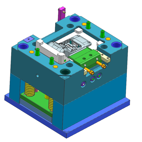
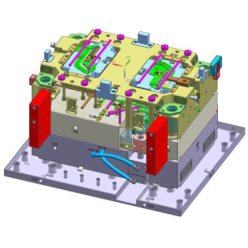
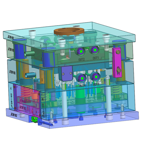
- Mold base + plates (support & alignment)
- Core/cavity inserts (critical fit control)
- Runner/gating (cold runner / hot runner as applicable)
- Cooling circuits (balanced layout and access logic)
- Ejection system (pins/sleeves/stripper; protection strategy)
- Wear/maintenance elements (where needed for longevity)
Engineering Priorities in Tooling Design
- DFM Before Steel Cutting (Risk Front-Loading) We flag problems early: sink/warpage, gas traps, weld lines, ejection marks, tolerance stack-ups, and CTQ stability.
- Precision Fit Control Where It Matters Critical inserts and shutoffs are engineered for repeatable fit and flash control—especially for cosmetic and optical parts.
- Stable Production Mindset Tooling is designed for repeatable output: cooling balance, venting logic, robust ejection, and consistent part release.
- Maintenance-First Tooling Logic Service-friendly structure reduces downtime: organized cooling layout, clear access to wear items, and faster troubleshooting paths.
- Clear Engineering Communication You get structured feedback and actionable next steps—not generic “OK to build” answers.
Tooling Applications We Commonly Support
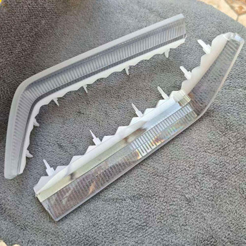
- Optical / Clear Parts (PC/PMMA): high-polish, stress control, cosmetic stability
- Cosmetic Housings / Enclosures: flash control, parting line stability, texture consistency
- Functional Structural Parts: rib management, CTQ control, robust ejection
- Insert Molding Tooling: reliable insert positioning + anti-shift strategies
- 2K / Two-Shot Tooling: bonding stability, cosmetic consistency, repeatable process windows
- Outdoor / Engineering Plastic Components: material selection, fit, warpage, and production stability considerations
DFM Review Before Steel Cutting
This review identifies major manufacturability and tooling risks before design release and steel cutting.
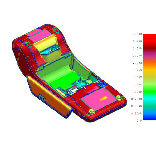
- Wall thickness consistency & fill balance
- Shrink/sink hotspots and countermeasures
- Warpage drivers (geometry + cooling direction)
- Gate location strategy & weld line control
- Venting plan to prevent gas traps/burns / short shots
- Ejection approach (part protection + mark control)
- Draft/undercut review (stuck-part risk)
- CTQ list + measurement plan (what to measure first)
Common Tooling Risks and Engineering Responses
These are common tooling risks we review during design, trials, and production preparation.
1) Flash / Parting Line Issues
Typical causes: poor shutoff design, insert fit drift, uneven clamp support, wear at critical edges
Countermeasures: strengthen shutoff design, tighten fit control on critical inserts, add wear-resistant elements where needed, verify alignment strategy, define clear polishing/EDM boundaries
2) Gas Traps / Burn Marks / Short Shots
Typical causes: insufficient venting, poor gate direction, trapped air in deep ribs/bosses
Countermeasures: venting strategy early in design, optimized gate direction, added vent channels on risk areas, controlled injection parameters during trials
3) Sink Marks / Surface Read-Through
Typical causes: thick sections behind cosmetic surfaces, rib/boss design, packing limitations
Countermeasures: geometry optimization suggestions in DFM, gating/packing support, cooling balance improvements, localized insert strategy when necessary
4) Warpage / Dimensional Instability
Typical causes: unbalanced cooling, uneven wall thickness, fiber orientation effects, residual stress
Countermeasures: cooling layout optimization, DFM-driven geometry recommendations, controlled processing window, fixture strategy for evaluation when required
5) Ejection Marks / Stuck Parts / Damage During Release
Typical causes: insufficient draft, wrong ejection layout, fragile features, poor surface/texture match
Countermeasures: ejection concept review (pins/sleeves/stripper), part protection design, draft recommendations, texture and polish boundary planning
Configurable Mold Design Options
We select tooling options based on your resin, appearance target, cycle time, and lifetime goals.
Runner & Gating
- Cold runner / Hot runner selection (based on volume, resin, and cost target)
- Gate type options: edge gate, submarine gate, fan gate, pin gate (as applicable)
- Weld-line positioning strategy and flow balance approach
Cooling Strategy
- Balanced cooling layout to reduce warpage and cycle drift
- Practical cooling access design for maintenance and uptime
- The temperature control concept is aligned with the resin behavior
Venting Strategy
- Primary venting plan + additional vent features for deep ribs/bosses
- Burn mark prevention logic and gas escape paths
Ejection Strategy
- Ejector pins/sleeves/stripper solutions based on geometry and surface requirements
- Mark control strategy for cosmetic faces
- Part protection logic for thin-wall or fragile features
Insert / Modular Strategy (for Iteration Control)
- Modular inserts to isolate risk areas and speed up changes
- Insert positioning and anti-shift design for stability
Surface & Texture Planning
- Polish level options for cosmetic/optical requirements
- Texture boundaries planning to avoid mismatch and witness lines
Mold Steel Selection Considerations
Mold Steel | Selection Considerations | Typical Applications | Notes |
|---|---|---|---|
P20 | Moderate-volume tooling where cost control is a priority | Conventional plastics, general tooling | Cost-effective, good machinability |
718H | Production tooling requiring improved hardness and dimensional stability | Larger/complex molds, engineering plastics | Good hardness and thermal stability |
NAK80 | Cosmetic tooling where polishability and surface consistency are priorities | High-precision / cosmetic tooling | Pre-hardened, good surface quality potential |
S136 / S136H | Corrosion-resistant or high-polish tooling applications | Corrosion resistance + high-gloss/optical | Corrosion resistance and high-polish potential; final suitability depends on resin, surface requirements, heat treatment, and tool specification |
Steel selection and expected tool life depend on resin, part geometry, surface requirements, production conditions, maintenance, and agreed project targets.
Surface Finish Planning
Surface finish is selected according to appearance, function, resin behavior, tool steel, and the agreed supplier scope:
- High Polish — high-gloss cosmetic or optical clarity targets
- Matte Finish — reduced reflection, more forgiving appearance
- Texture Finish — etched/engraved patterns for design intent and tactile feel
- EDM Finish — controlled EDM texture in functional areas
- Blasting — uniform satin texture, hides minor imperfections
- Chemical Etching — complex patterns/logos and controlled textures
From DFM to T0/T1 and Production
A practical tooling program should make each review and decision point visible:
- Project review and NDA: confirm application, material, volume, critical dimensions, appearance, and file status
- DFM and tool concept: agree on part risks, gating, cooling, venting, ejection, inserts, and maintenance priorities
- Mold design and manufacturing: complete design review, machining, assembly, and pre-trial checks
- T0 trial and validation: review dimensions, appearance, assembly fit, process behavior, and agreed CTQs
- T1/T2 correction and production handover: update the mold based on trial results and confirm the next validation or molding stage
Project Records and Engineering Communication
- Available by project requirement: DFM comments, tooling concept information, trial results, and agreed inspection or validation reports
- After T0: corrections can be planned from dimensional, assembly, appearance, and process results before T1/T2
- Production readiness: open risk items, maintenance access, wear areas, and next-step responsibilities are reviewed before handover
- Communication: initial feasibility response within 24 hours after receiving suitable information; detailed review timing depends on project scope
Request a Project Review
Send STEP, STP, IGES, IGS, X_T, PDF, ZIP, or product photos with key dimensions. NDA is available before quotation. Our engineering team will review the application, material, expected volume, critical requirements, and current project stage before recommending the next step.
- Contact / RFQ → Contact Us
- Email → info@jeancen.com